Added on June 5, 2019 at 00:04
This is an instruction on how to set up a MikroTik router step by step from scratch without using the factory configuration.
MikroTik router connection diagram:
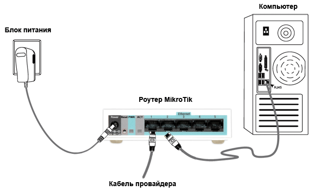
- Setting up a computer network card
- Entering MikroTik router settings
- Reset router settings
- Description of network interfaces
- MikroTik WAN interface setup
- Dynamic IP Setting
- Static IP Setting
- PPPoE Setup
- MikroTik local network setup
- LAN IP address assignment
- DHCP Server Setting
- Setting up a MikroTik Wi-Fi hotspot
- Firewall and NAT setup
- Изменение пароля доступа к роутеру MikroTik
- Сброс роутера MikroTik к заводским настройкам
- Теги
- Preparing for tuning
- Port setup and switching
- Internet connection setup
- Setting up network services (DHCP, DNS) and distributing the Internet to the local network
- Firewall setup
- Router security settings
- What to do after setup
Setting up a computer network card
In order to be able to enter the settings of the Mikrotik router on the computer, we will configure the network card to receive automatic settings.
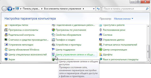
Windows7 — Control Panel
Let’s go to «Change adapter settings».
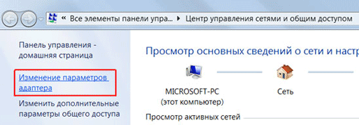
Windows7 — Change adapter settings
Right-click on «Local Area Connection» and select «Properties»
Windows7 — Local Area Connection
Click on «Internet Protocol Version 4 (TCP/IPv4)» and the «Properties» button.
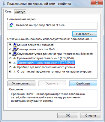
Windows7 — Internet Protocol Version 4 (TCP/IPv4)
If the network card does not automatically obtain an IP address from the 192.168.88.x subnet, try specifying it manually (for example: 192.168.88.21) or reset the Mikrotik router to factory settings.
Entering MikroTik router settings
You can configure your MikroTik router in different ways:
We will configure the Mikrotik router using the Winbox program.
Connecting to the MikroTik router:
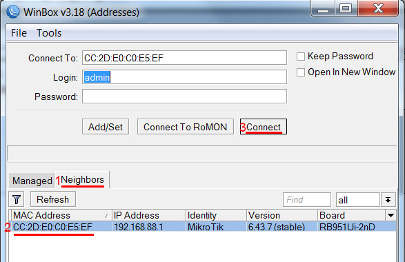
Reset router settings
Reset all settings of the MikroTik router.
When you log in for the first time, you will see a window like in the picture below. Click the Remove Configuration button and wait for the device to reboot.
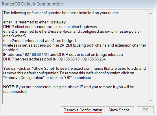
Clear MikroTik configuration
If you do not see this window, reset the settings through the menu:
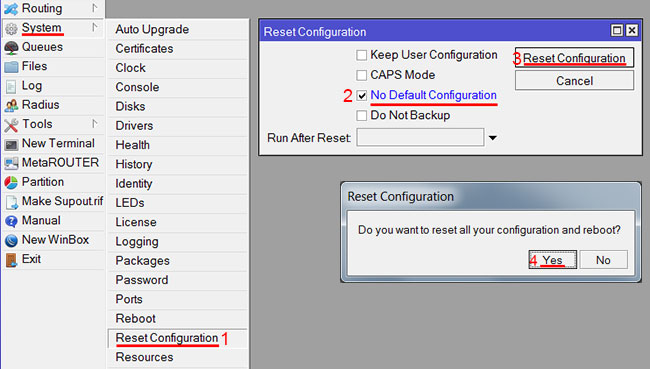
Reset MikroTik settings
Description of network interfaces
The MikroTik network interface configuration will look like this: the first ether1 port will be connected to the provider (WAN port), the remaining ether2-5 ports will work in switch mode to connect local network computers.
In order not to confuse network interfaces, we will describe them using comments.
We enter the MikroTik settings using the Winbox program.
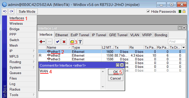
Description of MikroTik WAN interface
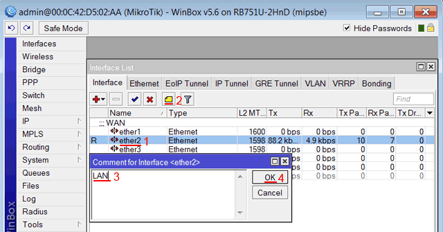
Description of MikroTik LAN interface
Now the list of interfaces clearly shows their purpose.
List of MikroTik interfaces
MikroTik WAN interface setup
If your ISP blocks access to the network by MAC address, then you must first change the MAC address of the WAN port of the MikroTik router. Otherwise, skip this paragraph.
To change the MAC address of the MikroTik port, open the New Terminal menu in the Winbox program and enter the command:
/interface ethernet set ether1 mac-address=00:01:02:03:04:05
, where ether1 is the name of the WAN interface, 00:01:02:03:04:05 is the allowed MAC address.
Change MAC address of MikroTik
To return the native MAC address of the port, you need to execute the command:
/interface ethernet reset-mac ether1
, where ether1 is the name of the interface.
Return native MAC address of MikroTik
Dynamic IP Setting
If the Internet provider gives you network settings automatically, then you need to configure the WAN port of the MikroTik router to receive settings via DHCP:
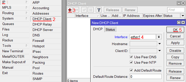
MikroTik DHCP client configuration
We have now received an IP address from the ISP, which is displayed in the IP Address column.
Obtaining an IP address via DHCP MikroTik
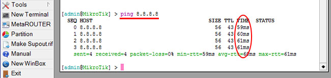
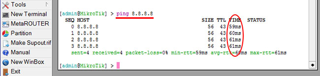
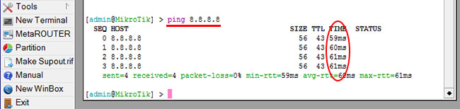
Check that there is an Internet connection:
As you can see, there are 60ms pings, which means the Internet is connected and working. You can stop the execution of the command with the keyboard shortcut Ctrl+C.
On computers connected to the MikroTik router, the Internet will not work until you configure the local network, Firewall and NAT.
Static IP Setting
If you use static network settings, you need to configure the WAN port of the MikroTik router manually.
Set up a static IP address and WAN subnet mask of the MikroTik port:
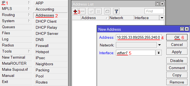
MikroTik static address setting
Set up MikroTik internet gateway address:
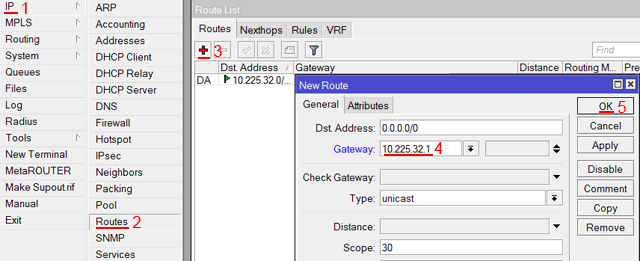
MikroTik gateway setup
Add MikroTik DNS server addresses:
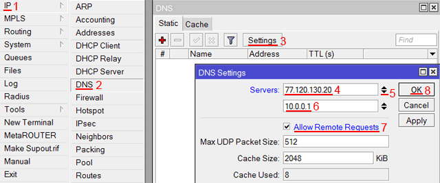
Setting DNS MikroTik
Check that there is Internet access:
PPPoE Setup
If you are using an ADSL modem to which a MikroTik router is connected via a network cable, you must first set the ADSL modem to Bridge mode.
Set up a client PPPoE connection on the MikroTik router:
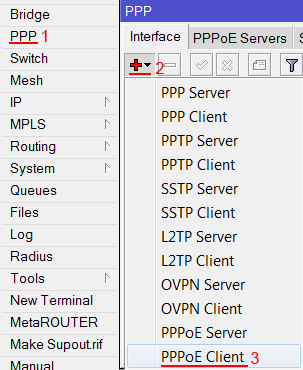
PPPoE MikroTik setup
Configuring MikroTik PPPoE connection parameters:
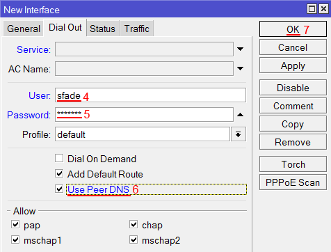
PPPoE MikroTik user and password setup
After creating a PPPoE connection, the letter R should appear in front of it, which indicates that the connection has been established.
PPPoE connection on MikroTik established
MikroTik local network setup
In order for computers connected to the router via cable and Wi-Fi to “see” each other, it is necessary to combine the wireless and wired MikroTik interfaces. If you have a router without Wi-Fi, then combine only wired interfaces.
Create a bridge-local association (bridge);
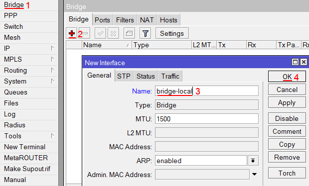
MikroTik local network setup
Add wired ethetnet ports 2-5 to the association:
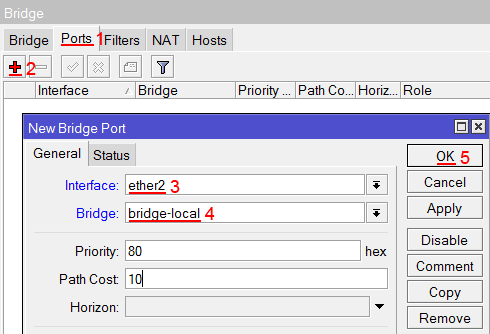
Combining MikroTik ethernet ports into a local network
Adding a Wi-Fi interface to the union.
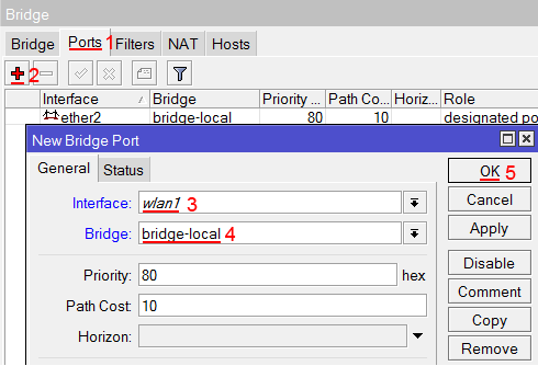
Combining MikroTik Wi-Fi interface into a local network
LAN IP address assignment
Set the IP address of the MikroTik local network:
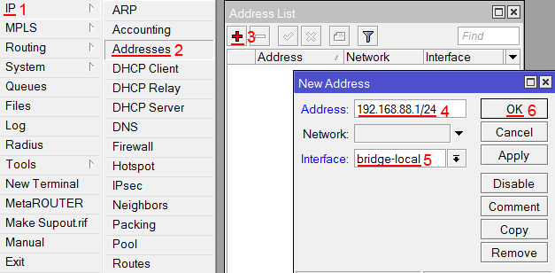
Assigning the IP address of the MikroTik local network
DHCP Server Setting
In order for computers connected to the router to receive network settings automatically, configure the MikroTik DHCP server:
Now we disconnect the network cable of the computer from the router and connect it again.
Setting up a MikroTik Wi-Fi hotspot
First you need to turn on the Wi-Fi module:
Setting up MikroTik Wi-Fi hotspot
Create a password to connect to the MikroTik access point:
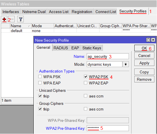
Setting the user and password for the MikroTik Wi-Fi point
Configure the parameters of the Wi-Fi point MikroTik:
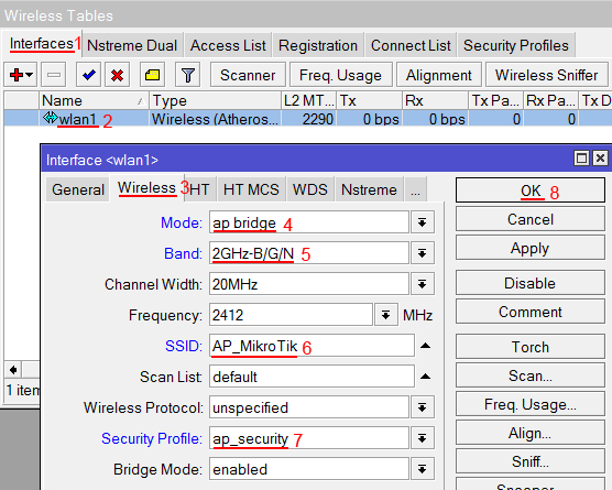
Setting up a MikroTik wireless access point
Now you can connect to the router via Wi-Fi.
On computers connected to the MikroTik router via Wi-Fi, the Internet will not work until you configure Firewall and NAT.
Firewall and NAT setup
In order for computers to access the Internet, you need to configure Firewall and NAT on the MikroTik router.
Open the New Terminal menu to enter commands.
NAT configuration is performed by the following commands:
ip firewall nat add chain=srcnat out-interface=ether1 action=masquerade
, where ether1 is the interface to which the Internet comes from the provider. For PPPoE connections, the name of the PPPoE interface is specified.
NAT settings are enough to make the Internet work.
Protect router — команды для защиты роутера:
ip firewall filter add action=accept chain=input disabled=no protocol=icmp
ip firewall filter add action=accept chain=input connection-state=established disabled=no in-interface=ether1
ip firewall filter add action=accept chain=input connection-state=related disabled=no in-interface=ether1
ip firewall filter add action=drop chain=input disabled=no in-interface=ether1
Protect LAN — защита внутренней сети:
ip firewall filter add action=jump chain=forward disabled=no in-interface=ether1 jump-target=customer
ip firewall filter add action=accept chain=customer connection-state=established disabled=no
ip firewall filter add action=accept chain=customer connection-state=related disabled=no
ip firewall filter add action=drop chain=customer disabled=no
Назначаем типы интерфейсов для защиты внутренней сети (external — внешний, internal — внутренний LAN):
ip upnp interfaces add disabled=no interface=ether1 type=external
ip upnp interfaces add disabled=no interface=ether2 type=internal
ip upnp interfaces add disabled=no interface=ether3 type=internal
ip upnp interfaces add disabled=no interface=ether4 type=internal
ip upnp interfaces add disabled=no interface=ether5 type=internal
ip upnp interfaces add disabled=no interface=bridge-local type=internal
Изменение пароля доступа к роутеру MikroTik
Чтобы изменить пароль доступа к роутеру MikroTik, выполните следующие действия:
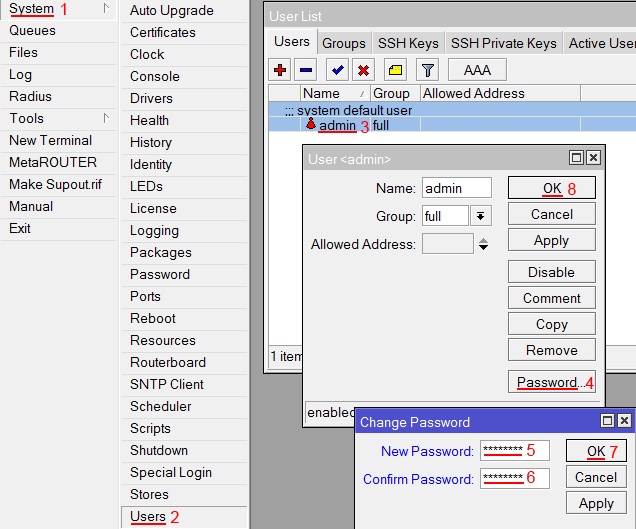
Изменение пароля доступа к роутеру MiktoTik
Сброс роутера MikroTik к заводским настройкам
Чтобы сбросить MikroTik к заводским настройкам выполните следующее:
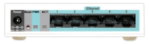
Сброс роутера MikroTik к заводским настройкам
Если вы войдете в настройки с помощью программы Winbox, то появится следующее окно:
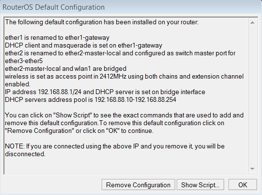
Быстрая настройка роутера MikroTik
C помощью кнопки OK можно выполнить быструю настройку роутера по умолчанию.
Кнопка Remove Configuration позволяет сбросить все настройки для последующей ручной настройки роутера.
Теги
За роутерами Mikrotik давно закрепилась слава «сложных» в настройке. Это действительно так, если говорить о начинающих. После обычных роутеров, где производитель практически за руку ведет пользователя от настройки к настройке, RouterOS пугает обилием возможностей и отсутствием привычных интерфейсов. Но не стоит пугаться, если вы имеете начальные знания по устройству и работе сетей, то очень скоро вы будете чувствовать себя как рыба в воде, а настройки иных роутеров наоборот покажутся вам ограниченными. Сегодня мы начнем с базовой настройки, чтобы научить ваш Mikrotik всему тому, что умеют обычные роутеры.
Научиться настраивать MikroTik с нуля или систематизировать уже имеющиеся знания можно на углубленном курсе по администрированию MikroTik. Автор курса, сертифицированный тренер MikroTik Дмитрий Скоромнов, лично проверяет лабораторные работы и контролирует прогресс каждого своего студента. В три раза больше информации, чем в вендорской программе MTCNA, более 20 часов практики и доступ навсегда.
В сети имеется достаточное количество инструкций по настройке роутеров этой марки, с разными подходами к этому процессу, поэтому мы не будем претендовать на истину в последней инстанции, а выразим наше видение этого вопроса. В первую очередь мы считаем, что возможности не должны опережать знания, поэтому не следует сразу браться за настройку сложных сетевых конфигураций. Лучше всего сначала разобраться в базовых настройках и только потом, по мере появления опыта переходить к более сложным схемам.
В свое время, когда вчерашний студент приходил на производство, ему говорили: «Забудь все чему тебя учили, и слушай сюда». Этот подход как никогда справедлив, если вы первый раз берете в руки Mikrotik, забудьте о предыдущем опыте с другими роутерами и готовьтесь осваивать новые подходы.
Прежде всего абсолютно неважно какая именно модель роутера у вас в руках, главное, что внутри находится RouterOS, а значит вам подойдет любая инструкция по настройке, за небольшими поправками, связанными с аппаратными ограничениями (скажем, если в вашей модели отсутствует Wi-Fi, то часть инструкции посвященную настройке беспроводной сети вы можете просто пропустить).
Поэтому для подготовки материалов по Mikrotik мы будем использовать виртуальные машины с RouterOS, прибегая к реальному оборудованию только чтобы показать какие-то специфичные моменты.
Preparing for tuning
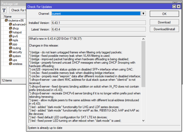
Secondly, starting with RouterOS 6.41, the switching settings have been changed, and if you want to use the current instructions, you must update the OS version before setting it up.
To do this, go to the manufacturer’s website in the Downloads section and download the latest version of Winbox — a graphical configuration utility, as well as the latest version of RouterOS. The packages presented on the page differ only in the architecture of your router, if you do not know it, then all suitable router models are listed next to it. Each section contains two packages: Main and Extra, the first is the main firmware, what is in your device out of the box, the second is additional packages that you can install yourself, we do not need them now.
To update, go to the Files section and upload the previously downloaded package from RouterOS, this can be done either with the Upload button or by simply dragging the file into the window. Then just reboot the device: System — Reboot.
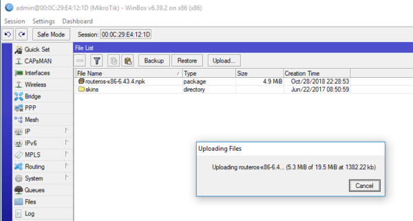
The next step is to update the RouterBOOT bootloader, for this we go to System — Routerboard and compare the current version with the available firmware, to update, click Upgrade and reboot the device again.
Port setup and switching
In older versions of RouterOS, there were two options for setting up switching: hardware, using a switching chip (through the master port) and software (through a bridge), in modern versions, only one option is used — through a bridge, while the switching chip will be used automatically, if possible, i.e. switching will still be done in hardware. We will touch on this point in more detail a little later.
By opening the Switch section, you can see which switching chips are installed in your router and which ports they serve:
For example, RB2011 is shown, which has two switching chips: the first serves the ether1-ether5 and spf ports, the second ether6-ether10. For ports served by one chip, hardware switching is available, between ports served by different chips, switching will be software. This should be taken into account when allocating ports, for example, if we allocate ether7 for the file server, and for ether2-ether5 clients, we will get an increased load on the device due to software switching.
For beginners, we will tell you one more news: Mikrotik does not have LAN and WAN ports, any port can be configured as you need. There are two external channels — we will configure two WANs, we need to serve two internal networks — no problem, we will create two switching groups.
Let’s leave the connection settings to the provider for now and combine the local interfaces into a switching group, for this we will need to create a bridge, go to the Bridge section and create a network bridge bridge1 there, in the comments we also indicate its belonging to the LAN.
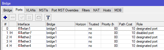
Then go to the Bridge — Ports tab and sequentially add the ether1-ether4 LAN interfaces to the bridge, pay attention to the Hardware Offload option that is active by default, which turns on hardware switching, if it is available.
So, the bridge has been created, ports have been added, now let’s go to Interfaces — Interface List and create a new list, which we will name local:
And then add our local bridge interface to this list:
Internet connection setup
Depending on your ISP, the method of connecting to the Internet may be different. Most often there is a direct connection when the provider distributes settings via DHCP or PPPoE connection (used by the federal provider Rostelecom). We will consider a direct connection further, however, if you have dial-up access (PPPoE or VPN), then you will need to go to the PPP section and create a dial-up connection of the Client type, an example for PPPoE Rostelecom is shown below. Specify the external interface ether5 as the interface to use:
Then, on the Dial Out tab, specify the data for connecting to the provider’s server and if you want to use its DNS servers, set the Use Peer DNS flag.
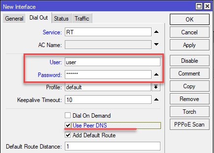
In the future, instead of the external interface ether5, you will need to specify your switched interface pppoe-out1.
You can read more about setting up VPN connections in Mikrotik in our article Setting up a VPN connection in Mikrotik routers.
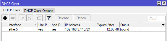
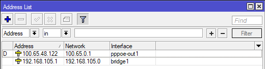
For dial-up connections, the DHCP client does not need to be configured, the interface will receive the address on its own, to make sure of this, open IP — Addresses again, where another address with the D (dynamic) index should appear and belongs to the dial-up connection.
Setting up network services (DHCP, DNS) and distributing the Internet to the local network
One of the most important network services is DHCP, today everyone is used to the fact that it is enough just to connect to the network, no matter if it is wired or via Wi-Fi, and all settings will be made automatically. Therefore, we will also start with DHCP, for this we will go to IP — DHCP Server and run the DHCP Setup server configuration wizard. The first step is to specify the working interface of the server — we specify the bridge1 network bridge that we configured for the local network.
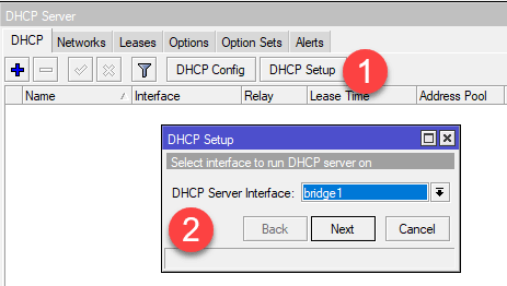
We complete the wizard and go to the Leases tab, here, as you connect, clients will appear to which your router will start issuing addresses. Pay attention to the «proprietary» feature of Mikrotik — it starts issuing addresses starting from the end of the range, i.e. from 199 to 100.
The next step is to set up a DNS server, it is very easy to do this, open IP — DNS and add upstream DNS to the list, these can be provider servers or public services, if you receive network settings from a provider via DHCP, then its DNS is servers will already be specified, they are located in the Dynamic Servers section and cannot be edited. If you add your own servers, they will have a higher priority, in our case the OpenDNS servers are specified.
In order for the server to serve requests from local network clients, do not forget to set the Allow Remote Requests flag.
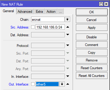
Basic network services are configured, but clients do not have access to the Internet yet, for this it remains to configure the address translation service — NAT. Go to IP — Firewall — NAT and add a new rule on the General tab in the Src field. Address, we indicate our local network 192.168.186.0/24, and in the field Out. Interface — external interface, in our case ether5. If you are using a dial-up connection, then you should specify it here, for example, pppoe-out1.
Now we can go to the client PC and make sure that the network settings are received and there is Internet access.
If you use torrents or other software that requires you to accept incoming connections, you should also configure the UPnP service, which allows network software to automatically forward the necessary ports on the router. Let’s open IP — UPnP, enable the service and move on to configuring interfaces by clicking on the Interfaces button.
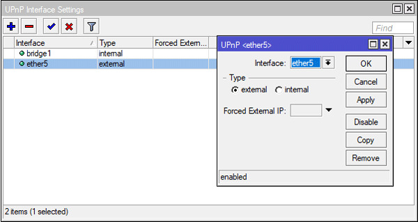
Now if we launch a torrent on the client, then automatically created rules for port forwarding are created in IP — Firewall — NAT, but if we close the torrent client, these rules will disappear. It is convenient and safe, and also allows you to fully use modern network applications.
Firewall setup
A firewall, also known as a firewall or firewall (both of these words mean a fire wall in English and German) is the most important part of the router and it would be a serious mistake to expose the device to the Internet without setting up a firewall. Therefore, let’s go to IP — Firewall — Filter Rules and get ready to stay here for a long time. In fact, it is much faster and easier to configure the firewall from the command line, but since our material is designed for beginners, we will do it using the Winbox GUI.
There are two basic firewall states: normally open, when everything that is not forbidden is allowed, and normally closed, when everything that is not allowed is forbidden. It is logical that the first policy should be used for the internal network, and the second one for the external network. By default, all chains of the Mikrotik firewall (and it is built on iptables) are in the ACCEPT state, i.e. allowed.
Let’s start with connections to the router itself or the input chain. First of all, let’s add a dummy rule allowing connection to the device from the local network. Why «dummy»? Because it is already allowed, but this rule will be our insurance against an accidental «shot in the foot» when we accidentally deny ourselves access to the device. The dummy rule placed first will fire before all the rules added later, unlike the default action, which will only fire if no rule matches.
So, add a new rule and specify Chain (chain) in it — input, Src. Address — 192.168.186.0/24 — your network range and In. Interface — bridge1, local interface. Actions are set on the Action tab, but since accept is already set by default, you can just click OK.
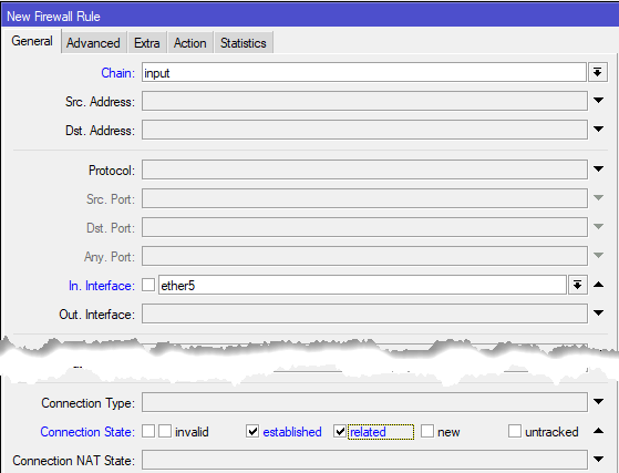
Using the following rule, let’s allow incoming connections on the external interface for already established and connected connections, create a new rule: Chain — input, In. Interface — ether5, set the established and related flags in the Connection State, since we accept the action again, we simply save the rule.
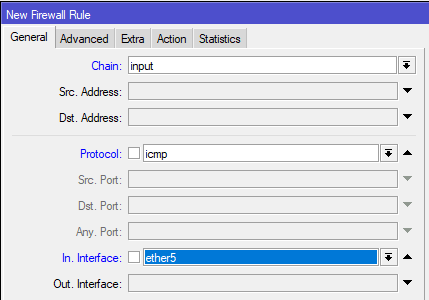
Below we have allowing rules for different types of incoming traffic. Be sure to allow the router to accept the ICMP protocol: Chain — input, Protocol — icmp, In. Interface — ether5. I CMP is not only pings, but also much more important things, for example, determining the minimum MTU of the communication channel (.
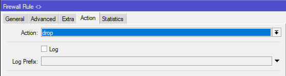
And the very last we create a rule that prohibits all other connections to the router: Chain — input, In. Interface — ether5, on the Action tab and set the drop action.
If you have a dial-up connection, then duplicate the rule for the interface that looks into the provider’s network, in most cases this is redundant, but it is quite justified from a security point of view.
Subsequently, additional allow rules should be placed below the rule for denying invalid, but above the rule blocking all incoming connections.
This set of rules is the minimum necessary and securely closes your device from the external network, it will not even respond to pings, external connections are also impossible. In our opinion, exposing device control, especially Winbox, to an external network is a bad idea, but if you need remote access to the router, then you should use other methods, for example, via VPN.
If you have basic knowledge of networking, working with the Mikrotik firewall cannot be called difficult, especially if you have worked with iptables (which is located «under the hood» here), understanding where the packet should come from and where to go — creating new rules should not cause trouble.
Let’s finish with the router’s own connections and move on to transit ones, i.e. from local network clients to the Internet and vice versa. The forward chain is responsible for this, but before moving on to the rules, you should pay attention to one more proprietary technology. It is called Fasttrack and provides for simplified packet transmission, which can significantly improve the performance of the router. However, this is achieved at the price that many firewall rules and other network technologies cannot be applied to such traffic (more details can be found on the official website).
So is Fasttrack needed? See for yourself, we took RB2011 and pumped a stream of 90 Mbps through it using Speedtest (at a rate of 100 Mbps) first with Fasttrack disabled:
In fact, we have already put the router on the shoulder blades, loading the CPU at 100% with just one test. In real life, a few network-heavy clients will do this even on a narrower channel. Unfortunately, it is no longer necessary to talk about some kind of complex traffic processing or any advanced network functions.
Enable Fasttrack and repeat the test:
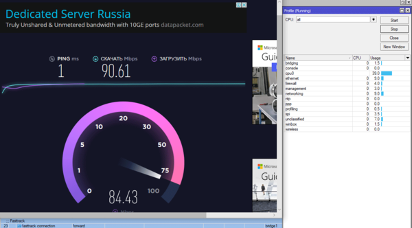
As you can see, the picture has changed significantly, the full utilization of the channel no longer causes the maximum load on the router, and there are quite enough resources left to implement some advanced network configurations or create complex traffic processing rules.
Therefore, first of all, let’s add the following rule: Chain — forward, Connection State: established, related, and on the Action tab, set the fasttrack connection action.
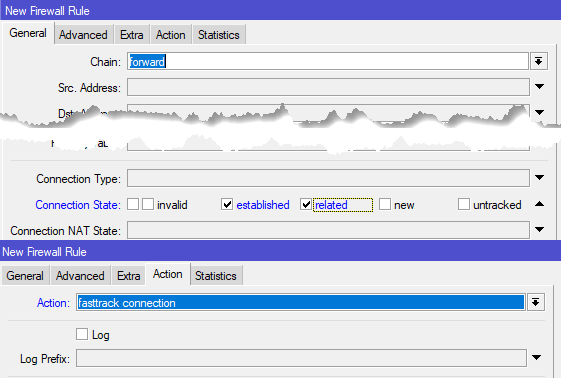
Thus, we will let through Fasstrack all packets of already established transit connections, and let’s be honest, there is no particular need to somehow handle such traffic on the router. Simple filtering can be easily achieved by pre-processing and marking packets, but for something more complex Mikrotik does not have enough resources, in this case it makes sense to think about a full-fledged router with a Linux-based proxy.
We do not touch the rest of the traffic from the local network to the Internet, because by default everything is allowed anyway, and any additional allowing rules will turn out to be empty shells that waste the computing resources of the router. Therefore, we will immediately close from access from the worldwide network. But before that, let’s allow the already established and connected connections in the same way: Chain — forward, In. Interface — ether5, Out. Interface — bridge1, below in the Connection State we set the established and related flags, the action is accept.
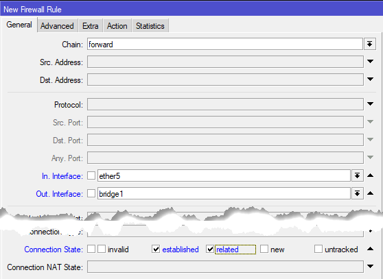
Deny packets in the invalid state: Chain — forward, In. Interface — ether5, Connection State — invalid, drop action. Below, if necessary, we place allowing rules for access from the outside to the local network.
Then we close from the outside world: Chain — forward, In. Interface — ether5, Out. Interface — bridge1, Connection NAT State — ! dstnat, drop action. The general principle here is the same as in the input chain, we allow established and connected connections, we forbid invalid, then our own rules come and prohibit all other traffic. The only point, in this rule, we set an exception for dstnat traffic, i.e. for forwarded ports, if this is not done, then the rules created by UPnP will not work correctly. As a result, you should get the following firewall configuration:
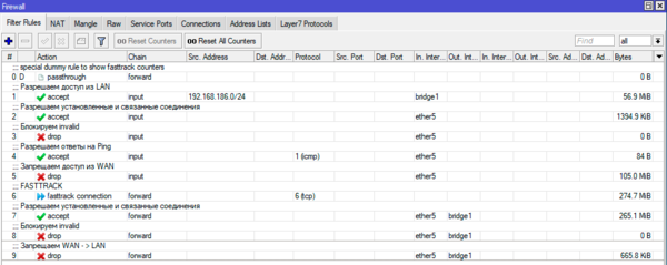
This is the minimum sufficient basic configuration that provides the necessary level of security and which we will rely on in our next materials.
Router security settings
The basic configuration of our router is finished, it can already be put into operation and serve the requests of local network clients. In the meantime, we will move on to additional settings that significantly affect the security of the device.
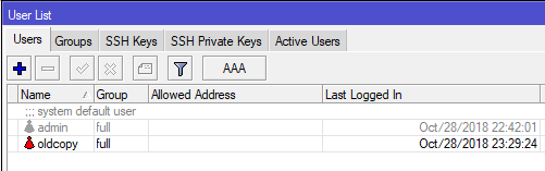
First of all, let’s go to IP — Services, the included network services of the router itself are listed here, feel free to disable all unused ones, including the web interface. To be honest, we do not see any point in it at all, since in appearance it completely repeats Winbox, but is somewhat less convenient to use.
Usually we leave only Winbox and SSH, for Winbox it will not be superfluous to set the range of valid addresses for connection, limiting them to the local network. If necessary, you can specify several networks (office network and branch network).
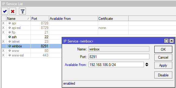
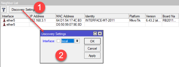
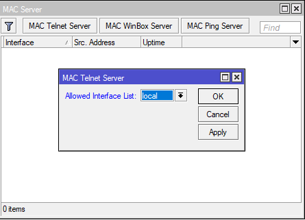
Device discovery and the ability to connect to it by MAC address is undoubtedly convenient, but also only in the local network. Open Tools — MAC Server and set the list of local interfaces in the Allowed Interface List.
Wi-Fi setup
It was not in vain that we moved this section to the very end, because the general steps for setting up a router with a wireless module and without it are absolutely the same. Therefore, it makes sense to complete all the general setup steps first, and then those who need to further configure their wireless network. We will not touch on all aspects of setting up Wi-Fi on Mikrotik here — this is the topic of a separate article, but we will only give basic settings.
If we open the Wireless section, we will see one or two wireless interfaces (for 2.4 + 5 GHz models), which will be disabled out of the box. But let’s not rush to turn them on, before setting up Wi-Fi it will not be superfluous to study the situation on the air. To do this, first press the Freq button. Usage and evaluate the channel load.
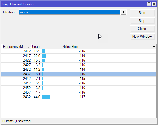
As we remember, in the 2.4 GHz band there are three independent channels that are preferable to use: 1 (2412 MHz), 6 (2437 MHz) and 11 (2462 MHz), so let’s start watching. We immediately see that the beginning of the range is quite busy and using the 11th channel may at first seem like a good idea.
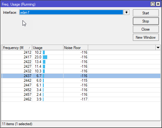
However, let’s not rush and watch a little longer, as it turned out — not in vain! On the 11th channel, from time to time, strong bursts of an incomprehensible nature were noted, according to which it could be assumed that there was not an access point there, but some other source of radiation. Therefore, the 6th channel can be called the most suitable in this situation.
Let’s close this window and press the Scanner button, which will show us all the access points operating in the range, while paying attention to the signal level. A signal of -35 dBm is taken as 100%, -95 dBm — 1%, the scale between these values is linear, i.e. -65 dBm — 50%.
As you can see, on channel 6 we have chosen, there is only one more or less powerful point with a signal of -59 dBm, which, however, is not very scary, intra-channel interference is quite easily overcome at the protocol level, which cannot be said about inter-channel ones. With this, it’s pretty good here, there are practically no powerful sources on adjacent channels, which cannot be said about the beginning of the range, where there is a very powerful point of -27 dBm on the first channel (in reality, it is 20 cm from the router we are testing).
We have decided on the channel, now let’s create a security profile for our wireless network in Wireless — Security Profiles. We leave only the WPA2 PSK protocol in it and specify the network key (Wi-Fi password).
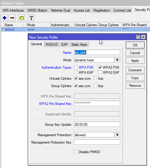
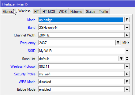
Now go to the wlan1 interface settings and on the Wireless tab change the following options in sequence: Mode — ap bridge — sets the access point mode, Band — 2GHz-only-N — only n-mode, Channel Width — 20 MHz — one of controversial settings, sets the channel width, but in conditions of real congestion of the 2.4 GHz band in urban areas, we believe that a stable 75 Mbps (with a standard channel width of 20 MHz) is better than 150 Mbps from time to time (at 40 MHz).
Next, specify the desired SSID, set the Wireless Protocol option as 802.11, specify the profile we created earlier in the Security Profile and turn off WPS: WPS Mode — disabled. This completes the basic wireless network setup.
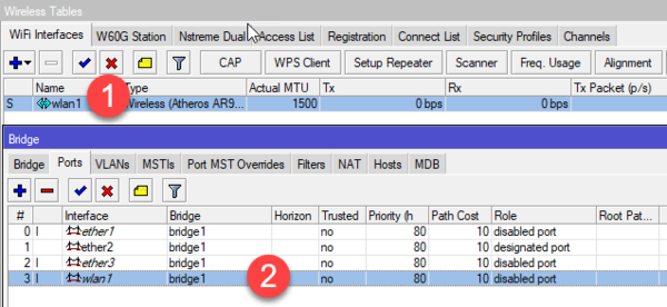
You can read more about setting up wireless networks in our article: Advanced Wi-Fi settings on Mikrotik routers. Access Point Mode
What to do after setup
We recommend that you create a backup copy after each change in the router settings, it will not take much time, but it will save you a lot of time in an emergency.
Despite the fact that the article turned out to be very extensive, there are no particular difficulties when setting up Mikrotik routers, if you understand what you are doing, then with the acquisition of experience, the setup will not take you much time. In our subsequent articles, we will also assume that the reader has basic setup at the level of this article and will not return to the issues described here.