

For several years of work, we have found for ourselves some golden mean in setting
Firewall MikroTik, and of course we want to share it with you.
We continue to configure the firewall, in the first part we protected our router, and
protected the internal network from the invasion of the evil mother’s coolhackers.
I’m studying iptables and am getting confused on the difference between FORWARD and OUTPUT chains. In my training documentation, it states:
If you’re appending to (-A) or deleting from (-D) a chain, you’ll want
to apply it to network data traveling in one of three directions:
This confuses me because, in my mind, packets leaving for a host WOULD be outgoing. So are there scenarios where a packet would be going to another computer but NOT be «outgoing»? How would iptables distinguish between the two?
asked Oct 17, 2013 at 23:36
OUTPUT is for packets that are emitted by the host. Their destination is usually another host, but can be the same host via the loopback interface, so not all packets that go through OUTPUT are in fact outgoing.
FORWARD is for packets that are neither emitted by the host nor directed to the host. They are the packets that the host is merely routing.
When you start digging into packet mangling and NAT, the full story is rather more complex.
answered Oct 17, 2013 at 23:43
To my understanding:
INPUT: dst IP is on the host, even it has multiple port with multiple subnet
OUTPUT: src IP is from the host, either port
FORWARD: Neither dst IP on the host nor src IP from the host
For example, to router A
answered Dec 25, 2015 at 19:28
1 silver badge5 bronze badges
Port forwarding is a seemingly trivial everyday task that should not cause any difficulties. Indeed, this is true in household routers, but if we are talking about Mikrotik equipment, then difficulties may not be long in coming. And all because RouterOS puts rich networking capabilities in the hands of the administrator, requiring in return an understanding of how networks work at least at a basic level. Of course, you can set everything up according to the ready-made instructions, but it is much better to understand each of your actions, and this article is intended for those who want to figure it out.
You can learn how to set up MikroTik from scratch or systematize existing knowledge in an advanced MikroTik administration course. The author of the course, a certified MikroTik trainer Dmitry Skoromnov, personally checks laboratory work and monitors the progress of each of his students. Three times more information than in the MTCNA vendor program, over 20 hours of practice and access forever.
- Port forwarding
- Hairpin NAT
- Create Lists
- Blacklist
- Whitelists
- Layer 7 protocol
- MAC Filtering
- Conclusion
- Interface List
- MikroTik Firewall Filter
- Firewall Filter Local input
- Stop!!! Stop!!! Stop
- Firewall Filter Local Forward
- Let’s start with the simplest, guest wifi
- Let’s continue with the VoIP chain
- Management vlan
- Local network
- Server network
Port forwarding
Forwarding, aka forwarding, ports — what is it? This is a technology that allows you to access hosts behind a router by redirecting traffic for specific ports from the external address of the router to the internal address of the host on the local network. This is made possible by NAT technology.
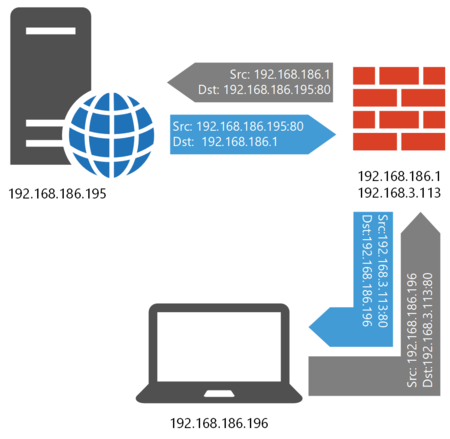
Let’s look at a small diagram that will help you understand how port forwarding works.
Let’s say a remote PC wants to access our web server, which is located behind a router in the local network. But it can only access the external address of the router (in our example, 192.168.3.113), to which we forwarded port 80 of the web server. Therefore, it forms a packet in which the router is the destination address and sends it to the recipient; it specifies its own address as the source address.
The router, having received such a packet, replaces the destination address from its own with the address of the web server, and, if necessary, it can also change the destination port. After that, the packet is sent to the local network and reaches the web server. The translation data is entered into a special NAT translation table.
Do I need to change the sender’s address? No, if the router acts as the main gateway of the network, and in the vast majority of cases it is. The web server will process the request, and since it does not know anything about the recipient’s network, the return packet will be sent to the default gateway, i.e. back to our router.
The router, based on the translation table data, will perform the reverse translation, this time replacing the source address from the internal address of the web server with its external address and send the packet to the host that requested it.
At first glance, everything is clear, so let’s move on to practice. RouterOS uses iptables as a network filter, so we will use its terms below. The NAT table uses two chains: PREROUTING — into which all packets that have arrived at the router fall, and POSTROUTING — all packets that have passed through the device pass through it. In PREROUTING, the dst-nat (DNAT) action is available to us, which allows us to change the destination address of the packet, in POSTROUTING, src-nat (SNAT) and masquerade will be available, which allow us to change the source address of the packet.
We pay special attention to this for a reason, since not understanding the process of passing a packet through the network filter chains can lead to significant difficulties when all the rules seem to be made correctly, but nothing works.
So for a packet from the client to the web server and back, the order of passing the chains will be as follows:
Note that the packet does not end up on the INPUT and OUTPUT chains that are used for the router’s own packets.
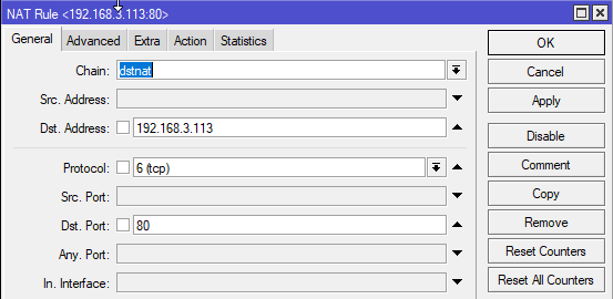
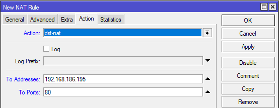
On the Action tab, specify: Action — dst-nat — replace the recipient address, To Addresses — 192.168.186.195 — the internal address of the web server, To Ports — 80 — the port on which the web server accepts connections. If the external and internal ports are the same, then the latter can be omitted.
Or run in the terminal:
/ip firewall nat add action=dst-nat chain=dstnat dst-address=192.168.3.113 dst-port=80 protocol=tcp to-addresses=192.168.186.195 to-ports=80
But that’s not all, after PREROUTING the packet will enter the FORWARD chain, in which, if you configured the router according to our instructions, any external packets are prohibited, except for connections initiated from the local network.
Let’s create a new rule. I P — Firewall — Filter Rules, where we add: Chain — forward — FORWARD chain, Protocol — tcp, Dst. Port — 80 — protocol and port, In. Interface — ether5 — the external interface of your router. Since the accept action is set by default in the new rules, you do not need to go to the Action tab.
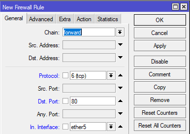
This rule should be located above the rule that prohibits transit traffic from the external network to the internal one.
Please note that if you are forwarding a port number change, say internal 3389 (RDP) to external 3390, then in the firewall rule you must always specify the internal port, i.e. 3389 because the packet has already gone through the PREROUTING chain and the recipient data in it has already been changed to the address and port of the internal server.
From the terminal, this can be done with the commands:
/ip firewall filteradd action=accept chain=forward dst-port=80 in-interface=ether5 protocol=tcp
It remains only to test the operation of our rules, let’s try to access the web server from an external host:
As you can see, everything works fine.
Hairpin NAT
All this is good, but exactly until we try to access the external address from the internal network. In general, such situations should be avoided, it is preferable to use domain names and a double-horizon DNS for access, when for external users the same name resolves to an external address, and for internal users — to an internal one. But this is not always possible. Trying to access from the inside at an external address, we get a connection error:
Why is this happening? Let’s look at another scheme:
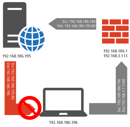
The first part of it is already familiar to us, the host sends a request to the external address of the router, it replaces the destination address with the address of the internal server and sends the packet to it, the sender address remains unchanged. But then the fun begins, the web server sees that the sender is in it on the same network and sends a response to it directly. But the sender sent a request to the external address of the server and is waiting for a response from it, so the response packet, the sender of which specifies the internal address of the web server, will be discarded and the connection will not be established.
What to do? Obviously, you need to somehow make the web server not respond directly to the client, but forward the packet back to the router. This is where the src-nat (SNAT) action comes in handy, which allows you to change the sender address that is in the POSTROUTING chain. In terms of Mikrotik, this setting is called Hairpin NAT.
To understand how it works, we prepared the following diagram:
Now our router not only changes the destination address, but also the source address, indicating its own internal IP as it. Having processed such a packet, the web server will send it back to the router, which will perform the reverse transformations (according to the translation table) and send it to the recipient. And since the node to which the request was sent will respond, in this case everything will work.
To configure on Mikotik, go to IP — Firewall — NAT and add: Chain — src-nat (POSTROUTING), Src. Address — 192.168.186.0/24 — range of your local network, Dst. Address — 192.168.186.195 — internal address of the web server, Protocol — tcp, Dst. Port — 80 — protocol and port.
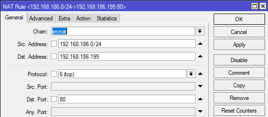
Please note that we specify the internal address and port as the destination address and port, since the packet has already passed the PREROUTING chain, where the recipient data has been changed. Unfortunately, not everyone understands this; in many instructions on the network, this rule contains an external address, needless to say, such a rule will not work.
Then go to the Action tab and specify: Action — src-nat (SNAT), To Addresses — 192.168.186.1 — specify the internal address of our router.
Through the terminal, this rule can be created as follows:
/ip firewall natadd action=src-nat chain=srcnat dst-address=192.168.186.195 dst-port=80 protocol=tcp src-address=192.168.186.0/24 to-addresses=192.168.186.1
In many other articles, the masquerade action is used for this rule, let’s see what the difference is. As a first approximation, both actions do the same thing — they change the source address of the packet, but src-nat works only with static addresses, but it allows you to specify any address as a source, masquerade works with dynamic addresses, but only the address of that the interface from which the packet is leaving. Due to the fact that masquerade determines the interface address with each request, this action requires more computing resources than src-nat.
In our case, all addresses are static, so using src-nat here would be more appropriate.
The rule has been created, let’s check its operation:
If you didn’t make any mistakes anywhere, everything will work as expected.
Summing up, we can say that there is nothing complicated in port forwarding, but only if you imagine in what order and how packets are processed, otherwise even such an elementary task can turn into lengthy torment out of the blue . Therefore, we hope that this material will be useful to you not only in practical terms, but also will allow you to increase your own level of knowledge.
Restricting access to certain Internet resources based on lists is a fairly popular filtering method, despite its shortcomings. Indeed, in most cases it is required to block a fairly small list of resources, say, a social network, which this method copes with quite successfully. In this article, we will talk about how to set up filtering by lists on Mikrotik routers, especially since RouterOS provides us with quite ample opportunities for this.
First of all, let’s talk about the features of filtering in the conditions of the modern Internet. The main trend of recent years is the massive transition to the HTTPS protocol. What does this mean? Unlike HTTP, which transmits data in clear text, HTTPS uses SSL encryption and all we can see for such a connection is the destination domain. We cannot see which pages the user visits on the specified domain and what data is transmitted from there.
It should also be understood that blocking through blacklists is applicable only to a small number of resources, for example, popular social networks, an attempt to filter all unwanted traffic in this way results in the need to constantly update the lists and can lead to a high load on the equipment. For such purposes, it is better to use specialized services.
Another option — white lists, despite their apparent simplicity and reliability, face another problem. Many sites actively use external resources from which they load scripts, fonts, styles, etc. and so on. and some of them may be critical to ensure full operation. There can also be problems with HTTPS if the browser is unable to check the status of the SSL certificate. All this will require a competent analysis and addition to the white list of all those nodes that are necessary for the normal operation of each of the allowed sites.
Create Lists
In the command line, the same action can be performed like this:
/ip firewall address-listadd address=yandex.ru list=WL
We can create as many such lists as we need, and the same address can be included in several lists at once. This is useful if you need to provide access to a different set of sites for different user groups. As a result, you should get something like this:
In this example, two lists are implemented: WL — white list and BL — black list. Usually one thing is used in real life, in our case, the creation of these lists is due to purely educational purposes.
We sorted out the domains, the users remained. There are two policies for applying the rules: allowed to everyone except for a user group and denied to everyone except for a user group. In any case, we have a user group that is either subject to restrictions or removed from their effect. In a well-designed system, such a group should be a minority, which will provide a minimum load on network equipment.
Or via command line:
Thus, we get a list of users, or several lists, in which the specified addresses will be located as long as the reservation is active on the server.
Blacklist
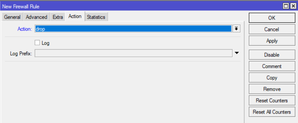
And finally, on the Action tab, specify the action, usually drop is indicated everywhere on the Internet, well, we will indicate it too.
This rule must be placed first in the FORWARD chain, above
The page doesn’t load, but the browser doesn’t understand what’s wrong and keeps trying to load it (i.e. the wheel is constantly spinning in the tab title), this loads PC resources and doesn’t bring clarity to the user. This is due to the fact that we just kill the packets — the drop action, and the sender does not understand why there is no answer. Therefore, for internal resources, it is better to use the reject action, which sends back a packet with a message that the resource is not available.
After replacing the action, when you try to visit the resource again, we will immediately see a message about its unavailability:
You can quickly add a rule via the command line like this:
Or on the command line:
Thus, filtering by blacklists is not particularly difficult. Everything depends on these same lists that need to be compiled and kept up to date. Loading ready-made lists from the Internet into the router is also not a good idea, because each packet will be checked for inclusion in the list, which can cause a serious load on the router, despite the fact that your users may never visit the vast majority of addresses from this list. Therefore, you should soberly assess your own resources and capabilities and apply lists where it is really needed.
Whitelists
Similar action via console:
This rule should also be placed first in the FORWARD chain.
Let’s add several addresses to the allowed ones, in our case yandex.ru and interface31.ru and try to open one of them. Yandex opens, but looks rather unusual.
Now let’s try to open our site. And here is the first unpleasant surprise:
What does this mean? The browser cannot verify the authenticity of the certificate, and since our site uses HSTS, access to it will not be possible, because such actions may indicate a downgrade attack, which HSTS should prevent.
In order for the browser to be able to check the certificate, we need to allow access to the information of the certification authority, the addresses of the required nodes can be found in the site certificate itself:
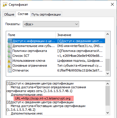
In our case, it turned out to be enough to add the ocsp.int-x3.letsencrypt.org node, the site loaded, but without comments, since they were implemented on a third-party resource and allowing access to it did not solve the problem. In this case, you will either have to deal with a long and painstaking clarification of the resources necessary for the work and whitelisting them, or refuse some of the functionality of the sites.
Or on the command line:
As you can see, technically it is not so difficult to organize access according to white lists, it is much more difficult to ensure the full operation of allowed sites, which requires quite a long and painstaking work to identify and add related resources to the list.
Layer 7 protocol
Layer 7 protocol is a technique for searching for specific occurrences in ICMP/TCP/UDP streams using regular expressions. At first glance, this is a rather interesting feature that significantly expands the degree of control over passing traffic, but there is one significant drawback. As the name implies, this type of filtering works at the application (L7) level, i.e. is fully processed by the CPU and even with a small number of rules can create a heavy load on the hardware, especially older (non-ARM) models.
Mikrotik developers themselves do not recommend using L7 to block sites, rightly noting that in most cases this will not work as intended, but at the same time you will waste the computing resources of the router. In our opinion, it makes no sense to use L7 for tasks related to accessing sites. Modern traffic is overwhelmingly encrypted and various kinds of structures for parsing URLs simply will not work, and it is quite possible to control access based on a domain name on L3 (which we did above).
For the same reason, many instructions posted on the Internet, where traffic was filtered by content, types of files or streams, used query parameters, etc., will not work. and so on. Although we still come across articles in which they try to block social networks or Youtube using L7, citing a large number of addresses, the use of CDNs, subdomains, etc. and so on. However, all this does not stand up to criticism, social networks and video hosting sites are perfectly blocked by a domain name.
We do not recommend using L7 in all those cases where the problem can be solved in another way, using it only for solving specific problems. For example, detecting and blocking any type of traffic.
As an example, let’s set the following task: to block the possibility of establishing SSH connections for network clients. A blunt solution to block outgoing connections to port 22 will not bring success, since the SSH server can run on an arbitrary port. Therefore, using special patterns, it is necessary to determine the presence of SSH traffic and somehow block it.
Where can I get patterns? Experienced users can run a network scanner (tcpdump, Wireshark) and analyze the available contents of the packets and, based on the information received, compose a regular expression. Or use the site l7-filter.sourceforge.net, but most of the patterns from there will not work. Firstly, the site is quite old, last updated in 2009, and secondly, many protocols have ceased to be used in the clear, and use SSL encryption. In this case, you will simply see an SSL stream, which is pointless to block, since you will block almost the entire Internet.
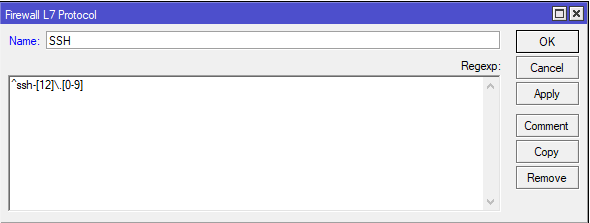
To solve our problem, first go to the IP — Firewall — Layer 7 protocol and create a new filter: in the Name field, write an arbitrary name, in our case, SSH, and in the Regexp field, enter the regular expression of the pattern:
You can also run the command in the terminal:
What to do next? The most obvious solution — to use this filter in firewall rules — is an example of what not to do. In this case, each packet will pass through the L7 filter, which will cause a heavy load on the router’s CPU.
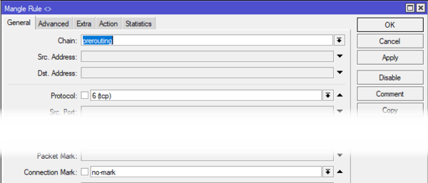
Therefore, we will go the other way and, based on the L7 filter, we will mark connections, which are much less than packets. Let’s go to IP — Firewall — Mangle and create a new rule: on the General tab, set Chain — prerouting, Protocol — tcp and Connection Mark — no mark:
On the Advanced tab, specify the use of the Layer 7 Protocol — SSH filter we created:
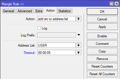
In the Action, specify the mark-connection action, set the connection mark New Connection Mark — SSH-CONN and be sure to set the Passthrough flag to pass the packet further down the chain:
Then add another rule: General — Chain — prerouting, Protocol — tcp and Connection Mark — SSH-CONN:
And in the actions add mark packet, New Packet Mark — SSH-PCK and remove the Passthrough flag:
All the same is quickly done on the command line:
/ip firewall mangleadd action=mark-connection chain=prerouting connection-mark=no-mark layer7-protocol=SSH new-connection-mark=SSH-CONN passthrough=yes protocol=tcpadd action=mark-packet chain= prerouting connection-mark=SSH-CONN new-packet-mark=SSH-PCK passthrough=no protocol=tcp
Many readers don’t work with the firewall past the Filter table, so what we’ve done in Mangle might seem like some special magic to them. Let’s briefly explain our actions. The first rule checks all untagged connections and those that coexist with the L7 filter, i.e. S SH connections are labeled SSH-CONN and continue down the chain. The following rule checks connections and labels all connection packets tagged as SSH-CONN with the label SSH-PCK.
Thus, we have marked all packets related to SSH connections, but we use the L7 filter only for connections, without burdening the router with checking each packet. Now we will prohibit the transit of such packets, for this we will return to IP — Firewall — Filter Rules and create a rule, on the General tab of which we will indicate: Chain — forward, Protocol — tcp, In Interface — bridge1 and Packet Mark — SSH-PCK:
On the Action tab, set the drop action. Same in console:
/ip firewall filteradd action=drop chain=forward in-interface=bridge1 packet-mark=SSH-PCK protocol=tcp
We also put this rule at the beginning of the FORWARD chain, and if you did everything correctly, then no one else will be able to establish an SSH connection from your network.
It should be understood that the above was just an example of how you can use the Layer 7 protocol on Mikrotik, in a real situation you should think several times and resort to the capabilities of L7 only when all other options have been exhausted. Also, try to describe in as much detail as possible the conditions for rules using L7 filters in order to minimize the load on the router’s processor.
MAC Filtering
Among the conditions in the firewall rules, there is a MAC address option, but only one address can be specified in one rule, i.e. for each MAC, you will have to create your own copy of the rule, which will increase the load on the device and make the rule set difficult to read.
Open IP — Firewall — Mangle and add a rule, on the General tab, specify Chain — prerouting, In Interface — bridge1, on Advanced in the Src field. M AC Address specify the MAC address of the desired device.
Same command line rule:
Conclusion
As you can see, the capabilities of RouterOS allow you to solve quite complex tasks using even inexpensive routers. But one should understand the limitations of all the above methods, realizing their advantages and disadvantages. And also correlate your requirements with the capabilities of the equipment. If these factors are understood and taken into account, then filtering by lists on Mikrotik will be an effective tool in the hands of an administrator. Otherwise, you will only get disappointment and other negative consequences. Therefore, we wish you prudence and remind you: a good administrator chooses the most appropriate tool for each task, which is a sign of professionalism. Fanaticism has never done anyone any good.
Interface List
Let’s create a separate sheet, where we list all our local interfaces, in which
are our users, just do not add all the interfaces, but only those
where there really is traffic. In my case, these are 5 interfaces
ether5.2 ether5.3 ether5.4 ether5.5, ether5.6 I call it this way
vlan interfaces, but in your case there may be different bridges and just interfaces.
/interface list add name=Local
/interface list member
add list=Local interface=ether5.2
add list=Local interface=ether5.3
add list=Local interface=ether5.4
add list=Local interface=ether5.5
add list=Local interface=ether5.6
Once again, don’t add all interfaces, even hypothetically you will
future use for internal networks, always add as needed.
Great, now we have a sheet with which we will work.
MikroTik Firewall Filter
In the first part, we got approximately the following configuration.
/ip firewall filter
add chain=input in-interface-list=ISP action=jump jump-target=ISP-Input
add chain=forward in-interface-list=ISP action=jump jump-target=ISP-Forward
add chain=ISP-Input connection-state=established
add chain=ISP-Input connection-state=related
add chain=ISP-Input connection-state=untracked
add chain=ISP-Input connection-state=invalid action=drop
add chain=ISP-Input jump-target=ISP-Input-Allow action=jump
add chain=ISP-Input action=drop
add chain=ISP-Forward connection-state=established
add chain=ISP-Forward connection-state=related
add chain=ISP-Forward connection-state=untracked
add chain=ISP-Forward connection-state=invalid action=drop
add chain=ISP-Forward connection-nat-state=dstnat
add chain=ISP-Forward action=drop
add chain=ISP-Input-Allow protocol=icmp
add chain=ISP-Input-Allow dst-port=22 protocol=tcp
add chain=ISP-Input-Allow dst-port=1701 protocol=udp
The main feature of our firewall is that you don’t need to
remember in what order to arrange the rules to open the necessary ports on the router,
you always work with ONLY one ISP-Input-Allow chain.
Now it’s time to discuss how we will configure the firewall for the rest
traffic, and it can be a lot and fly from different directions.
And so let’s start with a simple one, let’s take care of security.
Firewall Filter Local input
Let’s start with something simple, this will redirect all incoming traffic in the Local list to
custom chain! Let’s put this rule at the very top.
/ip firewall filter
add chain=input in-interface-list=Local action=jump jump-target=Local-Input
Now we will allow all established, related, untracked traffic in this chain.
add chain=Local-Input connection-state=established
add chain=Local-Input connection-state=related
add chain=Local-Input connection-state=untracked
It is also necessary to discard invalid.
add chain=Local-Input connection-state=invalid action=drop
Stop!!! Stop!!! Stop
Didn’t you notice that we started creating essentially the same rules for different
interfaces, it seems to me, or is it “overkill” ?! And you?
Personally, I don’t think it’s too much, it all depends on the situation, but in most cases
I’d rather make more rules and will always know which traffic goes through which
chains.
Actually, at this stage, we allowed packages that are associated with already installed
connections and packets that go by connection-tracker, untracked, with them
we’ll figure it out later.
Since we are setting up the input chain, we are working with packages that come directly
to the router itself.
Next, you need to understand that I cannot describe all possible scenarios and decide
exactly your case, but the meaning is approximately the following.
We will have a chain where we will redirect all the remaining packets, and as you probably remember
from the first part, these are only new packages, since only they remained for the terminator
principle. In such a chain, we will allow packages that need to be allowed for everyone
LAN interfaces.
add chain=Local-Input action=jump jump-target=Local-Input-All
In the name of the chain, we explicitly indicated that this is all traffic for local interfaces.
Now let’s consider when and what kind of traffic should be allowed.
In a good way, it is necessary to allow the router to ping, at least it will work
traceroute and some applications like to hammer the router, thereby checking
having a connection with him.
add chain=Local-Input-All protocol=icmp
If your router acts as a dns server for all networks, then why not
and not resolve it.
add chain=Local-Input-All protocol=udp dst-port=53
The issue of control and access to the router itself is always acute.
We need to be more selective in the firewall settings, let’s say we need to
allow Mikrotik management for its further configuration only from the ether5.3 interface
this is our certain management.
We are in the same chain, we will also indicate the interface.
add chain=Local-Input-All in-interface=ether5.3 protocol=tcp dst-port=22.8291
I.e. We also specified the interface.
And now we need to block all the remaining traffic, but not in the chain
Local-Input-All, and in Local-Input. So when the traffic is finished being processed
in the Local-Input-All chain, it will return to the Local-Input chain.
add chain=Local-Input action=drop
That’s it, now we have a configuration that allows from any local interface
access to dns and icmp, as well as from the ether5.3 interface connection directly
with ssh and winbox.
And if you need to allow something, then you work only with the Local-Input-All chain,
anything that is not explicitly allowed will be prohibited.
Firewall Filter Local Forward
And now let’s talk directly about passing traffic, namely traffic from local
networks. Let me remind you once again that we have five interfaces vlan ether5.2, ether5.3, ether5.4,
ether5.5 and ether5.6.
Before we start, we need to choose a concept or style, how it will be
build a general approach to the formation of rules and what parameter we will focus on
Firstly. Very often I see sentences “do it as it will”, which in
further leads to inflating the volume of rules in the firewall and further inconvenience
his control.
Of course, everything depends on the task and the set TOR, but since we work with you without
TK =), then it will be done in a simple way, namely, focus on our rules, on
a packet that came from a specific interface.
Create five rules
add chain=forward in-interface=ether5.2 action=jump jump-target=Forward-from-ether5.2
add chain=forward in-interface=ether5.3 action=jump jump-target=Forward-from-ether5.3
add chain=forward in-interface=ether5.4 action=jump jump-target=Forward-from-ether5.4
add chain=forward in-interface=ether5.5 action=jump jump-target=Forward-from-ether5.5
add chain=forward in-interface=ether5.6 action=jump jump-target=Forward-from-ether5.6
As you can see, for each logical IP interface we have created a rule that looks
into your own chain.
Create the last rule that drapes all packets
add chain=forward action=drop
Now our firewall has the concept of Normally closed firewall, everything that is not
what is allowed is forbidden and it will be necessary to remember that when adding VPNs or new
interfaces at you everything from them will be forbidden.
We also need to add two more rules, BEFORE our forward, namely:
add chain=forward connection-state=established
add chain=forward connection-state=related
add chain=forward connection-state=invalid action=drop
These rules are necessary in order to reduce the amount of traffic (pps) per rule
in custom chains, and also facilitate the convenience of configuration. These rules should
be always before forward/jump rules
And now let’s play with our chains.
Let’s start with the simplest, guest wifi
add chain=Forward-from-ether5.6 out-interface-list=ISP
Let’s continue with the VoIP chain
Let’s assume that we have a provision for phones, and we also have several
important servers.
Let’s create an address sheet so as not to produce entities
/ip firewall address-list
add address=192.168.5.3 list=ActiveDirectoryServers
add address=192.168.5.5 list=ActiveDirectoryServers
add chain=Forward-from-ether5.4 dst-address=192.168.5.2 protocol=udp dst-port=69 comment=»TFTP»
add chain=Forward-from-ether5.4 dst-address=192.168.5.2 protocol=udp dst-port=5060 comment=»SIP»
add chain=Forward-from-ether5.4 dst-address-list=ActiveDirectoryServers protocol=udp dst-port=53 comment=»DNS»
add chain=Forward-from-ether5.4 dst-address-list=ActiveDirectoryServers protocol=udp dst-port=123 comment=»NTP»
add chain=Forward-from-ether5.4 dst-address-list=ActiveDirectoryServers protocol=tcp dst-port=636 comment=»LDAP BOOK»
add chain=Forward-from-ether5.4 dst-address=192.168.5.4 protocol=udp dst-port=514 comment=»LOG»
Pay attention to TFTP and SIP, we do not need to allow related ports, for example,
as RTP 10000-20000 (in most cases), since we did not disable NAT helpers.
Hello, to all (who burns) lovers of helpers =))), but seriously, you should
choose for yourself how your approach will be built, or you disable the helper and
set up “everything and everything” or you assign part of the work to the helper, it’s up to you
you, both cases “take place”.
This is of course not included in this article, but remember one important nuance, data loss
authentication to the SIP server can lead to direct losses, in the form of a bill from your
provider, from here it is necessary to remember such a thing! Don’t neglect your security settings
in the local network, as practice shows, most often it is allowed from the local network
All! Install at least fail2ban on your PBX system and of course don’t forget
set it up.
Management vlan
A network in which to find various equipment requires a minimum of settings
add chain=Forward-from-ether5.3 dst-address-list=ActiveDirectoryServers protocol=udp dst-port=53 comment=»DNS»
add chain=Forward-from-ether5.3 dst-address-list=ActiveDirectoryServers protocol=udp dst-port=123 comment=»NTP»
add chain=Forward-from-ether5.3 dst-address=192.168.5.4 protocol=udp dst-port=514 comment=»LOG»
Local network
Here we will reward you
According to documentation https://docs.microsoft.com/en-us/troubleshoot/windows-server/identity/config-firewall-for-ad-domains-and-trusts
Please note that in most cases there will be more traffic on the Internet, so
the rule allowing access to the Internet is the first in order.
Server network
Of course, everything here is individual and for a specific task. I will try to make a collective
image
add chain=Forward-from-ether5.5 protocol=icmp
add chain=Forward-from-ether5.5 src-address=192.168.5.2 dst-address-list=voip.provider protocol=udp dst-port=5060
add chain=Forward-from-ether5.5 src-address=192.168.5.2 dst-address-list=voip.provider protocol=tcp dst-port=5060
add chain=Forward-from-ether5.5 src-address-list=ActiveDirectoryServers out-interface=ether5.2
add chain=Forward-from-ether5.5 src-address-list=ActiveDirectoryServers out-interface-list=ISP protocol=udp dst-port=53
Final table of firewall rules:
If you forgot something, don’t get angry, write to the group in the cart or VK, we will definitely fix it.
