

Time to read
The IPsec standard was created to provide security for the unsecured IP protocol. This is achieved by adding custom headers to the original package to encapsulate it, i.e. hiding original content.
Despite the emergence of newer protocols that allow you to organize a secure communication channel over the Internet, IPsec remains quite popular because it has a fairly high degree of security and good performance.
To properly set up a VPN using IPsec, you need to understand the basic principles.
IPsec is a set of protocols that can be divided into the following main groups:
IPsec can operate in two modes: transport and tunnel:
When a tunnel is created, an association is created called SA (Security Association). Each SA is created for a unidirectional connection. Since data must be transmitted in two directions, SAs are created in pairs. One SA pair is created for the AH protocol, the other for ESP. The created SAs are stored in the database of nodes (Mikrotik routers) that create the tunnel.
If an SA has been created on the node, then the VPN tunnel has been successfully established.
Each node has a Security Policy Database. Policies contain the following settings:
An IPsec connection is established in two phases: Phase 1 and Phase 2.
The initial authentication of the parties and the exchange of shared secret keys takes place using the IKE protocol. The operation of the IKE protocol consists of two stages:
Phase 1 The nodes agree on algorithms for the subsequent exchange of information and are authenticated. The shared keys are exchanged using the Deffie Hellman algorithm. As a result, a secure IKE SA channel is created.
Phase2 IPsec encryption keys are generated and policies are negotiated. This creates an IPsec SA connection
In the new version of the IKEv2 protocol, the process occurs in one phase with several steps.
The task of combining several networks in different offices is one of the most frequently encountered by system administrators. To solve it, various types of VPN and tunnel connections can be used, the choice of which may depend on many requirements and conditions. One alternative to tunnels and VPNs is a «pure» IPsec connection, which has both advantages and disadvantages. In this article, we will consider the implementation of such a connection between office networks (site-to-site) using Mikrotik equipment.
You can learn how to set up MikroTik from scratch or systematize your existing knowledge in an advanced MikroTik administration course. The author of the course, a certified MikroTik trainer Dmitry Skoromnov, personally checks laboratory work and monitors the progress of each of his students. Three times more information than in the MTCNA vendor program, over 20 hours of practice and access forever.
IPsec — a set of protocols for ensuring the protection of data transmitted in networks using the IP protocol. The main advantage of IPsec is a high level of security, today it is the best protocol for protecting transmitted data. It should also be noted a high level of performance, provided there are sufficient computing resources to work with cryptography. With regard to devices, Mikrotik IPsec allows you to get some of the highest results, especially on devices with hardware support for encryption.
But there are also disadvantages, they are also quite significant. I Psec is complex, both to set up and to understand how it works, it requires a deeper level of knowledge from the administrator and can cause serious debugging and troubleshooting difficulties. Also, IPsec does not use interfaces, but processes traffic based on its own policies, this also leads to a number of difficulties, ranging from traffic passing through the firewall and ending with the inability to apply routing for such connections. Some of the network configurations that are easily implemented using VPN and tunnels are basically impossible to build using IPsec.
Next, we will consider the combination of two office networks according to the scheme below:
Where LAN 1 with the range 192.168.111.0/24 and LAN 2 — 192.168.186.0/24 are the networks of the two offices that we will combine, and 192.168.3.107 and 192.168.3.111 — act as external white addresses in the network Internet. Our task is to provide transparent access of devices from one network to another through a secure communication channel.
- IPsec connection setup
- Firewall setup
- NAT Bypass and Fasttrack
- Conclusion
- Establishing a CA and issuing certificates
- Setting up an IKEv2 VPN server
- Setting up client connection in Windows
- Setting up client connection in Linux
- Mikrotik (Winbox)
- Create a permanent IPsec VPN
- Setting up IPsec on the router of office #1
- IPsec configuration for office #2 router
- Why all this
- Cisco FTD (Firepower Management Center)
- Verification
IPsec connection setup
An IPsec connection differs from both client-server VPN and stateless tunnels. Unlike the latter, we can always check the connection status, but the concept of client and server is missing here, in IPsec one of the devices acts as an initiator, and the second as a responder. These roles are not hard-coded and can change between devices, although we can assign a permanent role to a particular device if needed.
Let’s start the setup by defining encryption algorithms for each phase of the connection. Since we are connecting two of our own devices, we can ignore the compatibility requirements and adjust the encryption settings to our own discretion. But without fanaticism, do not forget that many Mikrotik devices are rather weak and do not have hardware support for encryption, and those that do support a different set of protocols.
So the popular RB750Gr3 (hEX) only supports SHA1/SHA256 — AES-CBC hardware acceleration, while the newer RB3011 already supports SHA1/SHA256 — AES-CBC and SHA1/SHA256 — AES-CTR. The desire to use strong ciphers is certainly commendable, but it should not outstrip the capabilities of the available hardware.
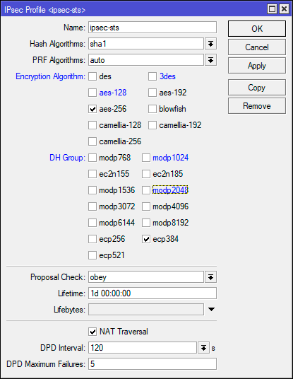
The first phase is key exchange and mutual identification of devices, the IP — IPsec — Profiles section is responsible for its settings, let’s go to it and create a new profile. For it, we specify: Hash Algorithms — sha1, Encryption Algorithm — aes-256, DH Group — ecp384. In the Name field, specify the name of the profile, in our case ipsec-sts (site-to-site).
In the terminal, to perform the same action, do:
/ip ipsec profileadd dh-group=ecp384 enc-algorithm=aes-256 name=ipsec-sts
These are quite strong cipher settings, for devices without hardware acceleration we would recommend limiting yourself to aes-128 and modp1024, although no one bothers to test the desired options and choose the most optimal one.
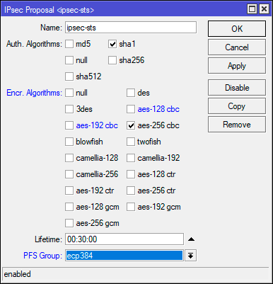
The second phase is the establishment of a secure connection and data transfer, the cipher settings for it are set in IP — IPsec — Proposal, let’s go to this section and create a new proposal. Specify Auth. Algorithms — sha1, Encr. Algorithms — aes-256-cbc, PFS Group — ecp384.
The same action in the terminal:
/ip ipsec proposaladd enc-algorithms=aes-256-cbc name=ipsec-sts pfs-group=ecp384
In this example, we used not the strongest ciphers, so the CBC encryption mode is the weakest, and if you have hardware support, you should use CTR or GCM. But do not forget about sufficient reasonableness, if the load on the device is high — lower the encryption level.
Now let’s go to IP — IPsec — Peer and create a new connection. In the Address field we specify the external address of the second router, in the Profile we select the profile we created at the previous stage, in our case ipsec-sts, and in the Exchange Mode field we specify IKE2.
/ip ipsec peeradd address=192.168.3.111/32 exchange-mode=ike2 name=sts-peer profile=ipsec-sts
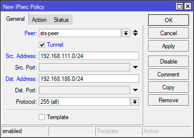
In general, what we have already configured is enough to establish a secure connection, but IPsec is not a VPN and works differently. In order for traffic to start being encrypted, it must comply with one of the IPsec policies, so let’s go to IP — IPsec — Policies and create a new policy. In the Peer field, we indicate the previously created connection, below we set the Tunnel flag for the connection to work in tunnel mode, in the Src field. Address, we indicate the range of our own network — 192.168.111.0/24, and in the Dst. Address — remote network range — 192.168.186.0/24.
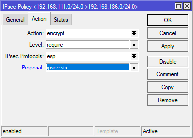
Then, on the Action tab, set Proposal — ipsec-sts, the proposal we created earlier.
For terminal, use the following commands:
/ip ipsec policyadd dst-address=192.168.186.0/24 peer=sts-peer proposal=ipsec-sts src-address=192.168.111.0/24 tunnel=yes
On the second node, you should perform similar settings, only specifying the external address of the first router as the address in Peer, and swapping the source network and destination network in Policy.
Firewall setup
We will assume that you are using a normally closed firewall configured in accordance with our recommendations. In order to allow an incoming IPsec connection, go to IP — Firewall — Filter Rules and add the following rules. The first of them allows the operation of the IKE key exchange protocol: Chain — input, Protocol — udp, Dst. Port — 500.4500, In. Interface — external interface, in our case ether1.
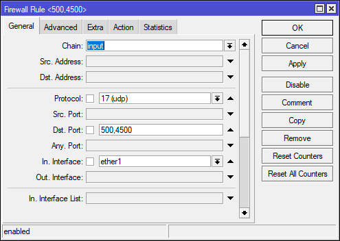
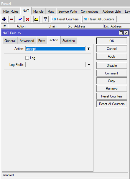
Note that we don’t specify an action anywhere, because by default all rules have accept as their action.
The same actions can be quickly performed in the terminal:
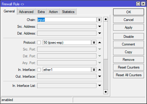
/ip firewall filteradd action=accept chain=input dst-port=500,4500 in-interface=ether1 protocol=udpadd action=accept chain=input in-interface=ether1 protocol=ipsec-esp
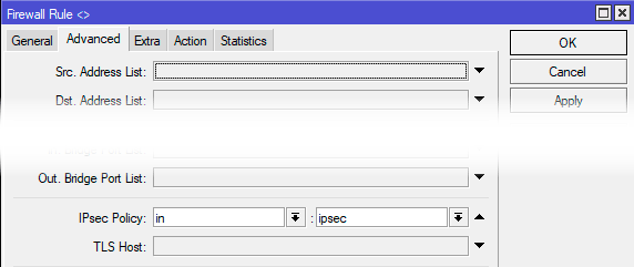
In order for packets from one network to get to another, their transit should be allowed. Let’s create one more rule: Chain — forward, In. Interface — external interface — ether1, then on the Advanced tab, specify IPsec Policy — in: ipsec. This will allow transit of any incoming packets that fall under any set IPsec policy.
/ip firewall filteradd action=accept chain=forward in-interface=ether1 ipsec-policy=in,ipsec
The same settings should be made on the second node.
NAT Bypass and Fasttrack
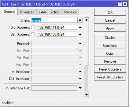
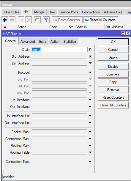
As we have already said, IPsec does not use interfaces, and therefore, the traffic processed by it, although it goes into a secure tunnel, continues to use the external interface as an outgoing interface, which can lead to a number of collisions. First of all, you need to exclude the processing of such traffic by the snat or masquerade rules. To do this, go to IP — Firewall — NAT and create a new rule: Chain — srcnat, Src. Address — 192.168.111.0/24 — local network range, Dst. Address — 192.168.186.0/24 — the range of the remote network, since the default action is accept, we do not explicitly specify it. We raise this rule to the very top, one should be the first in the srcnat chain.
You can add it via the terminal with the following command:
/ip firewall natadd action=accept chain=srcnat dst-address=192.168.186.0/24 src-address=192.168.111.0/24 place-before=0
The place-before=0 option allows you to put the rule at the very beginning of the chain.
If you use Fasttrack, then you should also exclude the processing of traffic passing through IPsec by this mechanism, for this you should add two rules. The first is for traffic from the local network to the remote: Chain — forward, Src. Address — 192.168.111.0/24 — local network range, Dst. Address — 192.168.186.0/24 — remote network range, Connection State — established, related.
The second rule for traffic from a remote network to a local one, it completely repeats the first one, only we swap the source network (Src. Address) and destination network (Dst. Address).
/ip firewall filteradd chain=forward action=accept place-before=0 src-address=192.168.111.0/24 dst-address=192.168.186.0/24 connection-state=established,relatedadd chain=forward action=accept place-before=0 src-address=192.168.186.0/24 dst-address=192.168.111.0/24 connection-state=established,related
Similar settings, taking into account the addresses, should be done on the second node.
Conclusion
After we have completed the configuration process, let’s go to IP — IPsec — Active Peers and make sure that the connection between the two nodes is established. If this is not the case, we check all the settings again and study the log file, most likely your encryption or identification parameters do not match.
Now let’s open IP — IPsec — Installed SAs. In terms of IPsec — SA (Security Association) — security association, denotes an established secure connection. A separate pair of SAs is created for each connection, since each SA is a unidirectional connection, and data must be transmitted in two directions. If we start data exchange between networks, say, ping a node of another network from a node of one network, then we will see that the Current Bytes counter data starts to change, and therefore encryption works and data is transmitted within a secure connection.
As you can see, if you understand the principles of IPsec at least at a basic level, then setting up a tunnel between two networks is relatively easy. We hope that this material will be useful to you.
Now that many people are setting up a VPN for remote employees, the choice of protocol is becoming more relevant than ever. On the one hand, there are PPTP and L2TP protocols supported by modern operating systems, which have a number of significant drawbacks and limitations, on the other hand, OpenVPN, which is good for everyone, but requires the installation of third-party software. At the same time, they somehow forget about the fast and secure IKEv2, a new protocol based on IPsec, also supported by all modern operating systems.
Why IKEv2? This protocol is part of the IPsec protocol group and provides a high level of security, including client authentication using a certificate, as well as server authentication by the client, which eliminates man-in-the-middle attacks. With support for hardware acceleration, IPsec on the hardware side shows a good connection speed compared to other VPN types in RouterOS and is very easy to configure from the client side, does not require adding routes.
The disadvantages include the rather complicated configuration of the server part, which requires the fulfillment of certain conditions and the presence of a basic amount of knowledge about the operation of IPsec. In this article, we will not delve into the theory, focusing on the practical side of the issue, confining ourselves to brief explanations of the need for certain settings.
Establishing a CA and issuing certificates
When we talk about using certificates for authentication, we mean the presence of a public key infrastructure (PKI) that forms a realm of trust, due to which it becomes possible to authenticate any subject of the infrastructure without involving third services and user lists. PKI is based on a certification authority — a CA that issues certificates and makes it possible to verify their authenticity using a root public certificate.
In our case, the certification authority will be created by means of RouterOS directly on the router. To do this, go to System — Certificate and issue the root certificate of our CA.
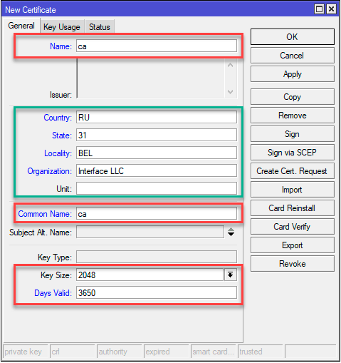
Required fields are indicated in red. Name — the visible name of the certificate and Common Name — the name of the subject to which the certificate was issued, in our case it is ca. Key Size — key size, keys smaller than 2048 bytes are not considered secure, Days Valid — certificate validity period, in our case 10 years.
The block highlighted in green is optional, but we advise you to fill it out so that in the future you don’t have to guess what kind of certificate it is and to whom and by whom it was issued.
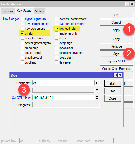
In the terminal, the same actions can be performed with the command:
/certificate add name=ca country=»RU» state=»31″ locality=»BEL» organization=»Interface LLC» common-name=»ca» key-size=2048 days-valid=3650 key- usage=crl-sign,key-cert-sign sign ca ca-crl-host=192.168.103.1
The next step is to issue a server certificate. Please note that the server must have a dedicated IP address and, preferably, a domain name. The last condition is not mandatory, but it is preferable, as it will allow you to get rid of the use of the address and in the event of a change in IP, you will not have to reissue certificates and change client connection settings.
On the Key Usage tab, specify the single value tls server and sign our certificate with the private key of the CA certification authority.
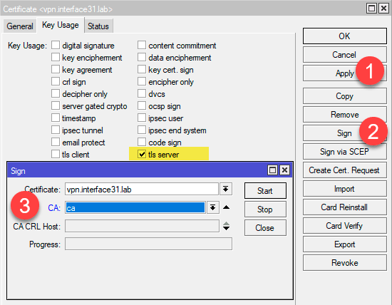
The same actions in the terminal:
/certificate add name=vpn.interface31.lab country=»RU» state=»31″ locality=»BEL» organization=»Interface LLC» common-name=»vpn.interface31.lab» subject-alt- name=DNS:»vpn.interface31.lab» key-size=2048 days-valid=3650 key-usage=tls-server sign vpn.interface31.lab ca=»ca»
Now you can issue client certificates, this can be done both immediately and later. There are no special requirements here, specify the most understandable value as the name, for example, the name of the employee or the name of the office. Because it will not be difficult to understand who owns the certificate with CN IvanovIA, unlike some faceless client3. Also pay attention to the Days Valid option, you should not issue client certificates for a long time.
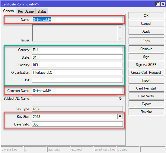
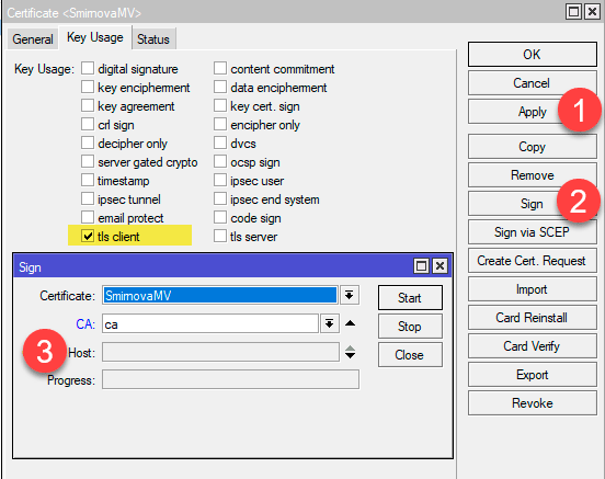
Terminal commands:
/certificate add name=SmirnovaMV country=»RU» state=»31″ locality=»BEL» organization=»Interface LLC» common-name=»SmirnovaMV» key-size=2048 days-valid=365 key- usage=tls-client sign SmirnovaMV ca=»ca»
For use on client devices, certificates should be exported, it is most convenient to use the PKCS12 format for this, which contains the client’s private key, its certificate and the CA root certificate in one file. To do this, select the certificate in the list and select the Export action in the right-click menu. In the Type field, specify PKCS12, and in the Export Passphrase, you must specify a password (at least 8 characters), otherwise the private key will not be uploaded.

The same can be done with the command:
/certificateexport-certificate SmirnovaMV type=pkcs12 export-passphrase=0123456789
Setting up an IKEv2 VPN server
Here we enter a rather complicated area of IPsec settings, the volume of the article does not allow us to dwell on the purpose of each setting in detail, so if you are not sure of your actions, then we do not recommend deviating from the settings below.
Let’s go to IP — IPsec — Profiles and create a new profile that sets the parameters for establishing a connection. We leave all parameters by default, except for the name, which should be given a meaningful name.
Or run the command in the terminal:
/ip ipsec profileadd name=IKEv2
Then let’s go to the Proposals tab, which contains the cryptographic parameters proposed for approval by connecting clients. Let’s create a new offer, which is formed taking into account the algorithms used by modern operating systems, and changing its composition can either weaken security or make it impossible for some clients to connect.
The default parameters are not suitable for us, therefore, in the Encr. Algorithms remove 3des and add aes-128-cbc, aes-192-cbc, aes-256-cbc.

A simple command is enough in the terminal:
/ip ipsec proposaladd name=IKEv2 pfs-group=none
Here we encounter one feature: the offers created via the terminal and Winbox contain a different set of parameters. What is created in the terminal fully complies with the requirements given above in the screenshot.
To issue VPN clients, we need a separate range of addresses, go to IP — Pool and create a new pool, in our case, the address range 10.20.0.100 — 10.20.0.199 will be used:
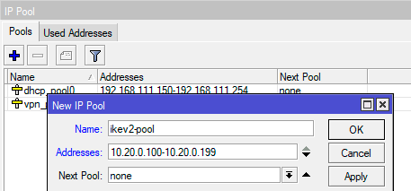
/ip ipsec mode-configadd address-pool=ikev2-pool address-prefix-length=32 name=IKEv2-cfg split-include=192.168.111.0/24
If you need clients to use internal name servers, for example, in Active Directory, then the System DNS flag should also be cleared and the addresses of the required DNS servers should be specified.
The command for the terminal will look like this:
/ip ipsec mode-configadd address-pool=ikev2-pool address-prefix-length=32 name=IKEv2-cfg split-include=192.168.111.0/24 static-dns=192.168.111.101,192.168.111.201 system -dns=no
On the Groups tab, let’s create a new group, there are no settings here, just specify a unique name:
/ip ipsec policy groupadd name=ikev2-policies
Then, on the Policices tab, we will create a policy template that will specify which traffic will be processed by IPsec and sent to the tunnel. In the Src field. Leave Address 0.0.0.0/0 in the Dst field. Address, specify the range allocated for the VPN network: 10.20.0.0/24, set the Template flag and indicate the group we created earlier in the Group field.
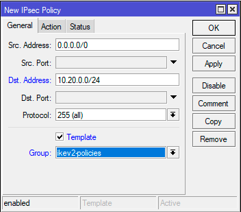
On the Action tab, in the Proposal field, specify the set of proposals we created earlier.

/ip ipsec policyadd dst-address=10.20.0.0/24 group=ikev2-policies proposal=IKEv2 src-address=0.0.0.0/0 template=yes
Then let’s go to IP — IPsec — Peers and create a new peer to accept connections. Immediately set the Passive flag, specify 0.0.0.0/0 in the Address field (we allow you to connect from anywhere), specify the profile we created in the Profile field, and specify the key exchange protocol — IKE2 in the Exchange Mode field.
In the terminal, to get the same result, run:
/ip ipsec peeradd exchange-mode=ike2 name=IKEv2-peer passive=yes profile=IKEv2
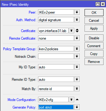
On the Identities tab, let’s create a new identification setting for connecting clients. There are a lot of custom fields here and you need to be extremely careful not to miss anything or mix it up. In the Peer field — specify the peer we created, Auth. Method — authentication method — digital signature, Certificate — server certificate. Policy Template Group — a group of policy templates — select the group we created, Mode Configuration — specify the configuration we created for clients, Generate Policy — port strict.
Command for terminal:
/ip ipsec identityadd auth-method=digital-signature certificate=vpn.interface31.lab generate-policy=port-strict mode-config=IKEv2-cfg peer=IKEv2-peer policy-template-group=ikev2-policies
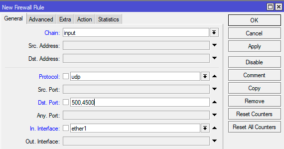
This completes the server setup, it remains only to add firewall rules that allow working with it. In order for clients to be able to connect to the server, let’s go to IP — Firewall — Filter Rules and add the rule: Chain — input, Protocol — udp, Dst. Port — 500, 4500, In. Interface — your external interface (in our case it is ether1). We do not specify an action, since the default is accept.
To add a rule in the terminal:
But that’s not all, in order for VPN clients to be able to access the internal network, one more rule needs to be added. On the General tab, specify Chain — forward and Interface — external interface, then on Advanced: IPsec Policy — in:ipsec.
Both rules should be placed higher than the prohibiting ones in each of the chains.
Setting up client connection in Windows
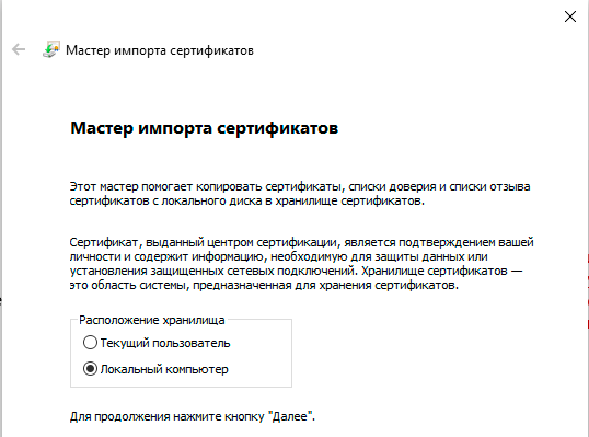
First of all, let’s import the certificate, for this you can simply double-click on the certificate file, in the Import Wizard that opens, specify Local Computer as the Storage Location, the rest of the parameters are accepted by default.
Then let’s create a new connection using standard tools. Let’s specify IKEv2 as the VPN Type, and Certificate as the Login Data Type. Also note that the Server Name or Address line must match the Common Name of the server certificate, otherwise the connection will fail.
After that, open the properties of the created connection and go to the Security tab, where we set the Authentication switch to Use computer certificates.
Now you can connect, if everything is done correctly — the connection will be successful. Check the route table:
As you can see, the route to our internal network 192.168.111.0/24 was added automatically and no manual client settings are required.
Setting up client connection in Linux
Let’s start with the certificate in the same way, but in this case we need a little more steps. We will assume that the certificate is located in the root directory of the user for whom we are setting up the connection. All subsequent commands should also be executed on his behalf.
Let’s go to the home directory and create a hidden folder for storing keys and certificates:
cd ~mkdir .ikev2
Now we need to export the root CA certificate, as well as the key and user certificate from the PKCS12 file. Let’s start with the root certificate:
openssl pkcs12 -in cert_export_SmirnovaMV.p12 -out .ikev2/IKEv2_CA.crt -nodes -nokeys -cacerts
Then export the client certificate:
openssl pkcs12 -in cert_export_SmirnovaMV.p12 -out .ikev2/SmirnovaMV.crt -nodes -nokeys
And his private key. When exporting a private key, we will be asked to set a password for it, the minimum password length is 8 characters. You cannot skip this step.
openssl pkcs12 -in cert_export_SmirnovaMV.p12 -out .ikev2/SmirnovaMV.pass.key -nocerts
At each of these steps, we will need to enter the passphrase specified when exporting the user certificate on the router.
And finally remove the password from the user’s private key:
openssl rsa -in .ikev2/SmirnovaMV.pass.key -out .ikev2/SmirnovaMV.key
During this action, you will need to enter the password that you specified when creating the key.
In order to be able to create VPN connections in the graphical interface, install the necessary plugin for Network Manager:
sudo apt install network-manager-strongswan
After that, the VPN IKEv2 connection settings will become available to you.

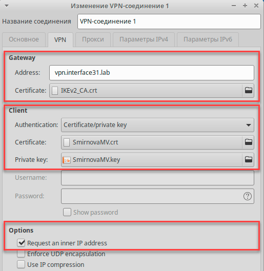
Connection settings are quite simple. In the Gateway section, specify the server address and the path to the root CA certificate. In the Client section, set Authentication: Certificate/private key and specify the paths to the client’s certificate and private key. And in the Option section, be sure to set the Request an inner IP address flag. This completes the connection setup, you can connect.
If we check the routing table after connecting, we will not find a route to the office network, but it will be available:
But there is no mistake here. It’s just that Linux does more correctly in this situation, instead of a route, an appropriate IPsec policy is created in the system, which directs traffic to the internal network into the tunnel according to what we specified in the client configuration (Mode Configs) on the router.
Mikrotik (Winbox)
Starting IPsec configuration:
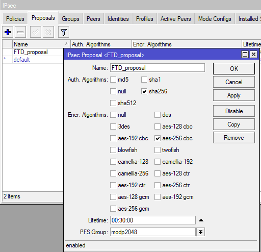
Next, open the proposals tab
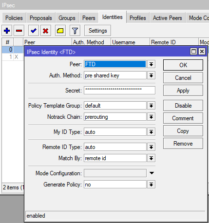
Go to the Identities tab
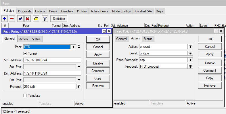
Now let’s move on to the main thing — setting Policies
The main snag in Mikrotik’s configuration is that it is possible to specify only one subnet for one policy. If we need to link 2 subnets, this is not a problem. In the case of multiple subnets from different ranges, the first difficulty arises. It is necessary to make a policy for each subnet.
On the second contribution (Actions) indicate
Repeat the settings for each subnet we want to add to the tunnel. From each local to each remote.
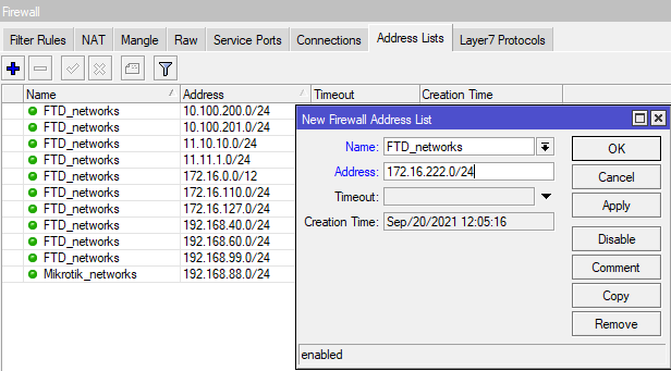
Now you need to configure the Firewall. Let’s start by creating address sheets.
IP — Firewall — Address Lists
Our task: to create 2 sheets. One — FTD_networks — with the networks that we will receive. And the second — Mikrotik_networks — with local networks on Mikrotik.
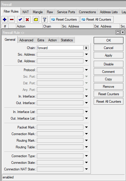
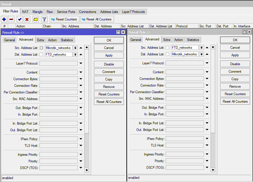
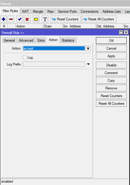
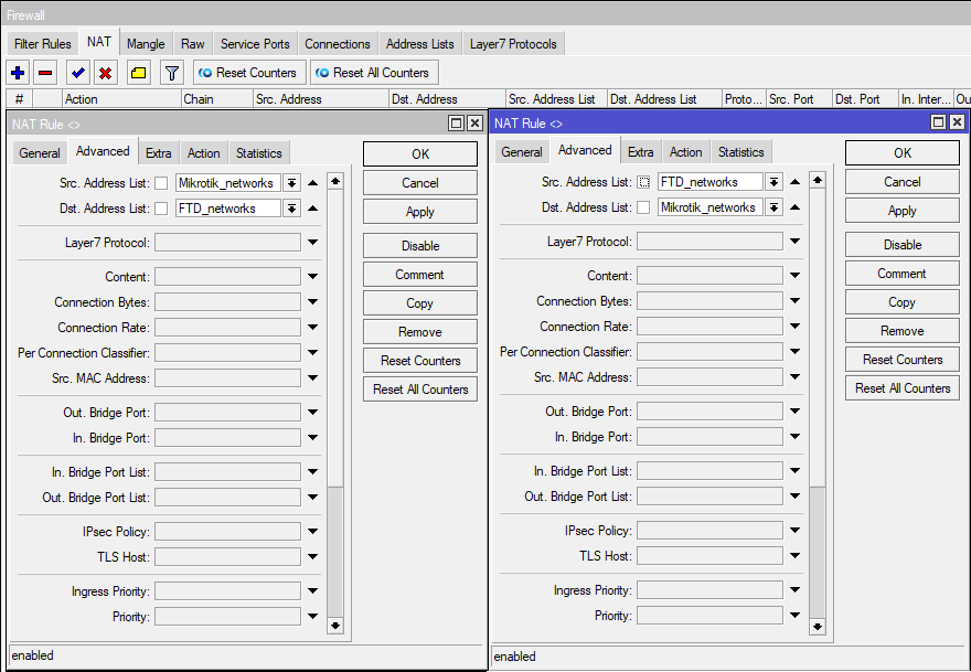
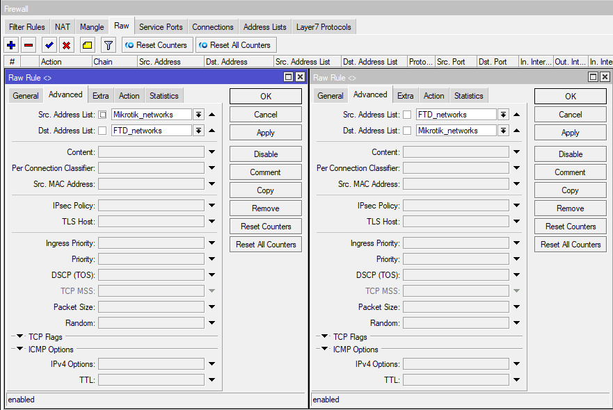
Go to the Filter Rules tab. Here we need to create allow rules for our subnets so that the router will let them through.
And the second rule, where Source and Destination Address List are swapped. Our permissive rules must be higher than those forbidding! Therefore, they need to be dragged up if they are not.
Go to the NAT tab.
We need to make exceptions for our subnets so that they do not fly into normal NAT masquerading.
As in the filtering rules, you need to make 2 rules, swapping Source and Destination in the second one. And also, raise these rules above the masquerade rule.
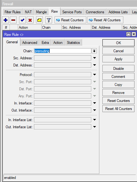
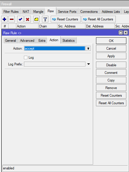
Go to the Raw tab.
Here, similarly, you need to make 2 rules for prerouting
As in the previous tabs, you need to make 2 rules, swapping Source and Destination in the second one.
This completes the setup by Mikrotik. You can move on to the answer.
Create a permanent IPsec VPN
Site-to-site tunnel allows you to create a permanent secure VPN channel between two offices via the Internet. Each office has its own LAN and needs to access the other office’s LAN.
The normal operation of the IPsec tunnel can be prevented by NAT and Fasttrack rules. This must be taken into account and create bypass rules before or after setting up a VPN.
IPsec tunnel won’t work without NAT traversal and Fasttrack!
NAT translation rules (masquerade) change the source address and the router will not be able to encrypt a packet with a source address that differs from that specified in the IPsec policy. This will result in no network traffic going through the tunnel and packets will be lost.
The NAT traversal rule helps solve this problem.
/ip firewall nat
add chain=srcnat action=accept place-before=0 src-address=192.168.1.0/24 dst-address=192.168.2.0/24
/ip firewall nat
add chain=srcnat action=accept place-before=0 src-address=192.168.2.0/24 dst-address=192.168.1.0/24
The rule must be above all other rules in the NAT table.
If Fasttrack is used on the router, then this will also break the operation of IPsec, since the packets will bypass the IPsec policies. To solve this problem, add allow rules accept in front of Fasttrack.
It is necessary to allow transit traffic on both routers in two directions — from the office 1 network to the office 2 network and in the opposite direction:
/ip firewall filter
add chain=forward action=accept place-before=1
src-address=192.168.1.0/24 dst-address=192.168.2.0/24 connection-state=established,related
add chain=forward action=accept place-before=1
src-address=192.168.2.0/24 dst-address=192.168.1.0/24 connection-state=established,related
The picture below shows an example of a rule for traffic from the Office 1 network to the Office 2 network. The rule for the reverse direction of traffic will differ in Src addresses. Address 192.168.2.0/24 and Dst. Address 192.168.1.0/24
However, creating rules in the Filter table can significantly increase the CPU load in cases where many tunnels are used and a significant amount of traffic is transmitted. In such a situation, it is better not to use the Filter table for bypass rules, but to create them in IP/Firewall/RAW. This will allow you to not track connections and exclude the processing of the rules above, which will reduce the load on the CPU.
/ip firewall raw
add action=notrack chain=prerouting src-address=192.168.1.0/24 dst-address=192.168.2.0/24
add action=notrack chain=prerouting src-address=192.168.2.0/24 dst-address=192.168.1.0/24
After adding the rules on both routers, the following rules should be present in the RAW table:
Setting up IPsec on the router of office #1
1. Set the Profile for phase 1
Profiles define a set of parameters that will be used for IKE negotiation in phase 1.
dh-groupe — group selection Deffie Hellmanenc-algoritn — encryption algorithmname — profile name
/ip ipsec profile
add hash-algorithm=md5 dh-group=modp2048 enc-algorithm=3des name=Office2-ike1
When choosing an encryption algorithm, the impact on link performance should be considered. If the channel speed is important to you, choose the algorithms that Mikrotik supports in hardware. The Mikrotik wiki has a table.
2. Adjust Proposal for Phase 2
Proposal or offer — information that will be sent by IKE services in order to establish SA connections according to certain policies.
auth-algorithms — authentication algorithm; enc-algorithms — encryption algorithm; name — policy name (specify the same as in the profile to make it clear which profile the policy belongs to); pfs-group (Perfect Foorward Security) — generates additional session keys based on the keys of the parties and agrees on them using the Deffi Hellman algorithm (even if the shared key is intercepted, they will not be able to decrypt the traffic).
/ip ipsec proposal
add auth-algorithms=sha256 enc-algorithms=3des name=Office2-ike1 pfs-group=modp2048
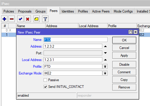
3. Add Peer
This specifies the information needed to establish a connection between the IKE daemons of two nodes. This connection will then be used to negotiate keys and algorithms for SA connections.
address — public address of the remote routername — any friendly nameprofile — profile used for connection
UDP/4500 (IPsec NAT traversal) and UDP/500 (IKE) ports must be available for IPsec to work. Check your firewall to make sure there are no rules blocking traffic to these ports.
/ip ipsec peer
add address=10.2.100.1/32 name=Office2-ike1 profile=Office2-ike1
4. Create an Identity — a secret phrase for identification.
Select Peer and enter Secret ID. The more complex the Secret, the better, so it is better to use a password generator to create it.
/ip ipsec identity
add peer=Office2-ike1 secret=MySecret!
5. Finally, create a Policy that controls the secure channel networks/hosts.
src-address — source network address (office 1) dst-address — destination network address (office 2) src-port — source port (any — all ports) dst-port — destination porttunnel — tunnel modeaction — what to do with packets (encrypt — encrypt)proposal — which offer to usepeer — which node to establish a connection with
/ip ipsec policy
add src-address=192.168.1.0/24 src-port=any dst-address=192.168.2.0/24 dst-port=any tunnel=yes action=encrypt proposal=Office2-ike1 peer=Office2-ike1
IPsec configuration for office #2 router
Start by adjusting Profile and Proposal.
/ip ipsec profile
add hash-algorithm=md5 dh-group=modp2048 enc-algorithm=3des name=Office1-ike1
/ip ipsec proposal
add auth-algorithms=sha256 enc-algorithms=3des name=Office1-ike1 pfs-group=modp2048
Then add Peer and Identity.
/ip ipsec peer
add address=10.1.100.1/32 name=Office1-ike1 profile=Office1-ike1
/ip ipsec identity
add peer=Office1-ike1 secret=MySecret!
Finally, create a Policy.
/ip ipsec policy
add src-address=192.168.1.0/24 src-port=any dst-address=192.168.2.0/24 dst-port=any tunnel=yes action=encrypt proposal=Office1-ike1 peer=Office1-ike1
Below, on the slide, all the IPsec settings of the second node in Winbox are presented:
After configuring the two nodes, a tunnel connection will be established and IPsec Security Associations will be created on the routers:
/ip ipsec
active-peers print
installed-sa print
Additionally, you can check the operation of policies:
/ip ipsec
policy print status
IPsec tunnel established. You can check traffic flow by sending an icmp request (ping) from a workstation on one network to a workstation on another network.
Why all this
This note is written to ease the way for those who will face the problem after me. The task seems trivial, but as usual, problems came up in the process, which had to be solved by the method of a long study of mana and endless reconfigurations. For some reason, there is very little information on the Internet on setting up Cisco Firepower Threat Defense (FTD), and even more so in conjunction with Mikrotik.
Cisco FTD (Firepower Management Center)
The firewall and NAT configuration logic from the FTD side is almost the same, but the tunnel itself is configured differently. Let’s start with him.
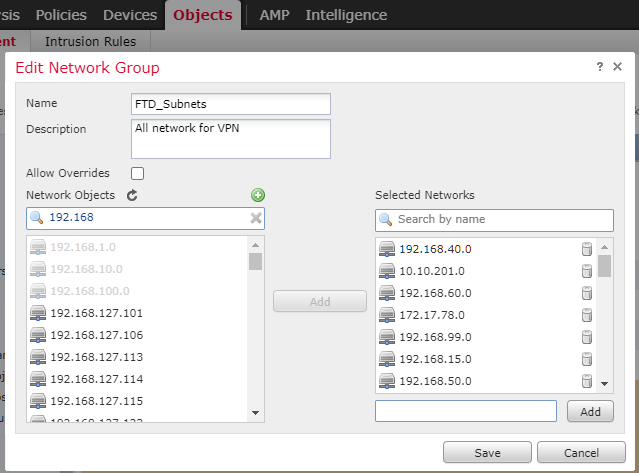
First, we need to create groups for the subnets that we send to the tunnel and which we receive.
Go to Objects — Object Management. Add Group
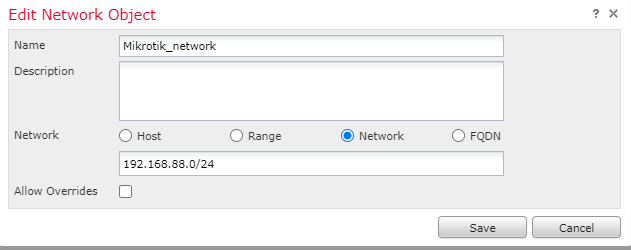
In my case, for the subnets we are giving away, this is FTD_Subnets. We add to Selected Networks all the subnets that we want to give to the tunnel. And we get one subnet, so we set it through Add network — Mikrotik_network.
Despite this, it is better to define a group even if there is only one subnet inside, since in the case of an extension, it will be much easier to add a new subnet to the group than to add new rules for each object.
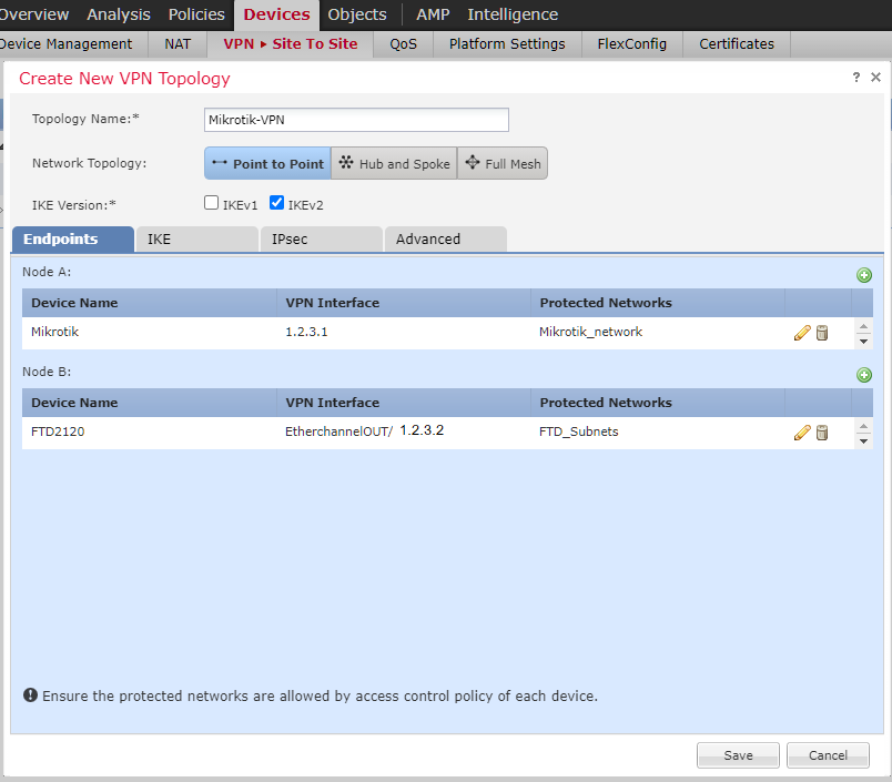
Let’s move on to creating a tunnel. Devices — VPN -Site to Site. Add VPN Firepower Threat Defense.
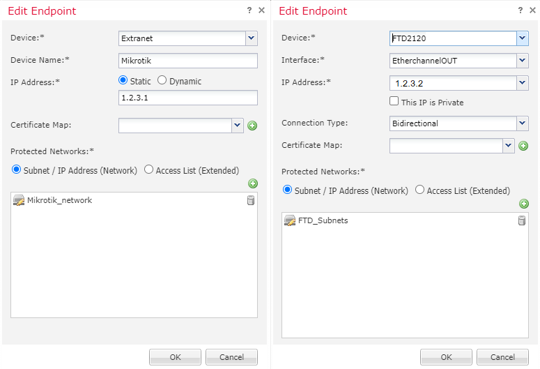
In the Endpoints tab, specify:
Node A is Mikrotik
Node B is our local FTD
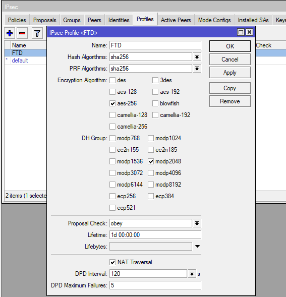
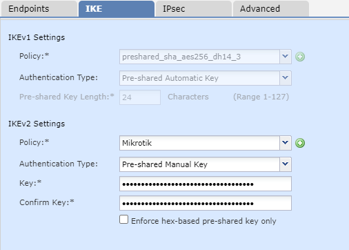
On the IKE tab fill in IKEv2 Settings:
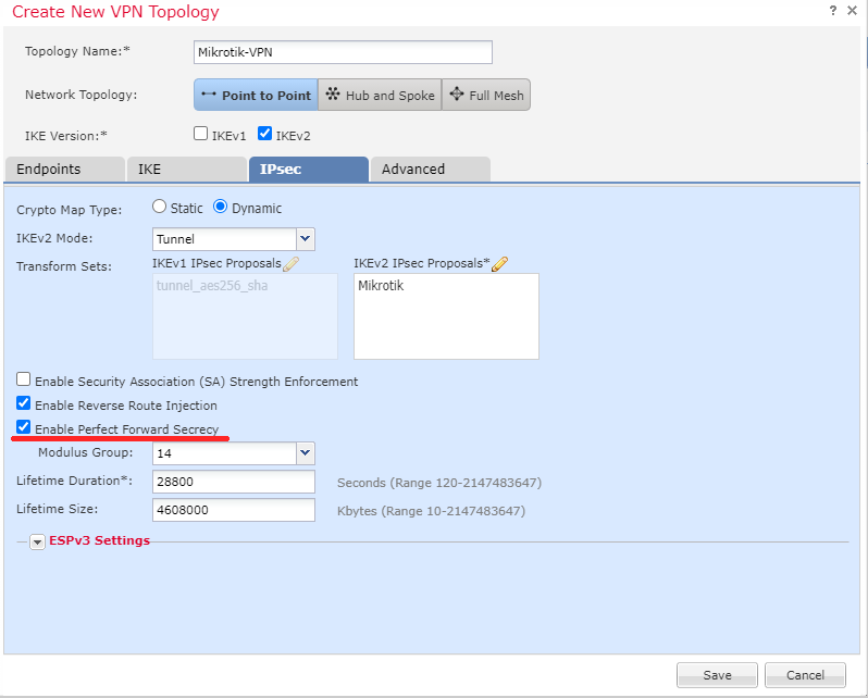
On the IPsec tab, fill in:
Without enabling this feature, only one Policy will be active on Mikrotik at a time. That is, only one subnet will work.
Leave all other parameters as default. Don’t forget to save the configuration.
Now we need (similarly to Mikrotik) to make NAT allow rules and exceptions.
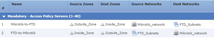
Go to Policies — Access Control and create 2 rules
From the zone Inside to Outside, from Mikrotik_network to FTD_Subnets, Allow. Inspection and Logging can be added to taste. And the second rule, where everything is reversed.
In my case, the zone Inside_Zone is the zone behind which are all the subnets that need to be sent to the tunnel. Outside_Zone — Internet zone. If there are additional zones (DMZ, interconnects to other subnets), then you need to make rules for them.
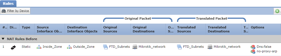
Go to Devices — NAT and create a Static, Manual NAT Rule:
Rule must be higher than NAT for local subnets.
Verification
FTD, unfortunately, does not show as much information as we would like. you can see the status of the tunnel and possible errors along the path Devices — VPN — Troubleshooting.
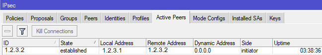
From the Mikrotik side, we must first see on the IPsec — Active Peers tab our connection in the established state
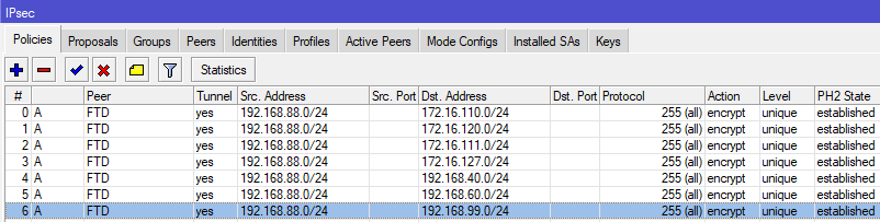
and secondly, in IPsec — Policies all policies must become A (active) and PH2 State established.
If the policies hang in the no phase 2 state, all but one, then first of all we look at the Level (unique) setting in Policies on Mikrotik and the Enable Perfect Forward Secrecy checkbox in the tunnel setting on cisco FTD.
UPD: in the comments it was suggested that a more serious protocol can be set in the DH group. For example, ecp521 from Mikrotik (group 21 from Cisco) — this practically does not affect the data transfer rate and CPU load of Mikrotik (checked).
Also, Filter Rules on Mikrotik are redundant if there are default rules (accept inout ipsec policy) that allow everything in and out of ipsec.
Initially, we need to make sure that both of our parties have a «white» routable ip address. Theoretically, all this can be passed through NAT if the device is inside the network, but this complicates the configuration, and not all providers allow one-to-one NAT nowadays.
Let’s start from the side of Mikrotik. I assume that it has a fresh firmware (in my case it is 6.48.4), and it is already configured as a router with a «white» address outside.
