
- Для чего нужен VPN IpSec и какой роутер MikroTik выбрать
- Identities
- Настройка интернета для VPN клиентов L2TP в MikroTik
- Нужна настройка VPN L2TP MikroTik?
- Encapsulating Security Payload (ESP)
- Как настроить VPN L2TP+IpSec между MikroTik и VPS CentOS 8
- 1. Настройка VPN сервера L2TP на удаленном VPS сервере на CentOS 8
- 2. Настройка L2TP клиента на MikroTik
- Application Examples
- Site to Site IPsec tunnel
- Site 1 configuration
- Site 2 configuration
- NAT and Fasttrack Bypass
- Road Warrior setup using IKEv2 with RSA authentication
- RouterOS server configuration
- RouterOS client configuration
- Windows client configuration
- macOS client configuration
- iOS client configuration
- Android (strongSwan) client configuration
- Linux (strongSwan) client configuration
- Road Warrior setup with Mode Conf
- IPsec Server Config
- Apple iOS (iPhone/iPad) Client
- Android Client Notes
- RouterOS Client Config
- Shrew Client Config
- Basic L2TP/IPsec setup
- RouterOS server configuration
- RouterOS client configuration
- Site to Site GRE tunnel over IPsec (IKEv2) using DNS
- Site 1 (server) configuration
- Site 2 (client) configuration
- IKEv2 EAP between NordVPN and RouterOS
- Дополнительные опции L2TP-клиента
Для чего нужен VPN IpSec и какой роутер MikroTik выбрать

Одна из самых популярных опций в роутере для бизнес сегмента. Позволяет объединить в локальную сеть удаленные офисы. Масштабирование такой сети ограничивается прошивкой RouterOS:
- 4 level – до 200 подключений;
- 5 level – до 500 подключений;
- 6 level – без ограничений.
ну а практическая реализация от быстродействия самого Mikrotik. В первую очередь стоит обращать внимание на аппаратную поддержку IpSec, отсутствие которой сопровождается обработкой всего блока шифрования через CPU маршрутизатора. Это характеристика в первую очередь влияет на количество пропускаемого трафика. Если ваш маршрутизатор(роутер) MikroTik начинает тормозить от передачи файлов к примеру 200-300Мб по каналу IpSec, стоит задуматься над переходом на маршрутизатор, который имеет аппаратную поддержку IpSec. Из актуальных моделей это может быть:
Как было указано выше, в зависимости от версии RouterOS визуальное расположение разделов для настройки VPN IpSec будет отличаться. Чтобы привести оба примера, первым будет рассмотрен вариант для версии RouterOS 6.44 и старше, а за ним последует зеркальная настройка второго маршрутизатора(роутера) MikroTik, только с прошивкой RouterOS 6.43 и младше. Схема будут состоять их двух подключений, будет введено наименование маршрутизаторов: MikroTik-1 и MikroTik-2.
Identities
Identities are configuration parameters that are specific to the remote peer. Main purpose of an identity is to handle authentication and verify peer’s integrity.
Read only properties
Настройка интернета для VPN клиентов L2TP в MikroTik
Этот вопрос будет вынесен за рамки данной статьи, т.к. относится с дополнительным сервисам для VPN клиентов. Таких сервисов может быть множество и все они имеют индивидуальных характер(для тех кто ищет: нужно настроить и разрешить DNS запросы и Masquerade).
Нужна настройка VPN L2TP MikroTik?
Настройка сервисов на маршрутизаторах MikroTik: подключение интернета, DHCP, brige, VLAN, WiFi, Capsman, VPN, IpSec, PPTP, L2TP, Mangle, NAT, проброс портов, маршрутизация(routing), удаленное подключение и объединение офисов.
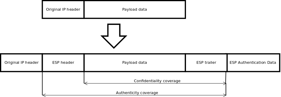
Encapsulating Security Payload (ESP)
ESP packages its fields in a very different way than AH. Instead of having just a header, it divides its fields into three components:
- ESP Header — Comes before the encrypted data and its placement depends on whether ESP is used in transport mode or tunnel mode.
- ESP Trailer — This section is placed after the encrypted data. It contains padding that is used to align the encrypted data.
- ESP Authentication Data — This field contains an Integrity Check Value (ICV), computed in a manner similar to how the AH protocol works, for when ESP’s optional authentication feature is used.
In transport mode ESP header is inserted after original IP header. ESP trailer and authentication value is added to the end of the packet. In this mode only IP payload is encrypted and authenticated, IP header is not secured.
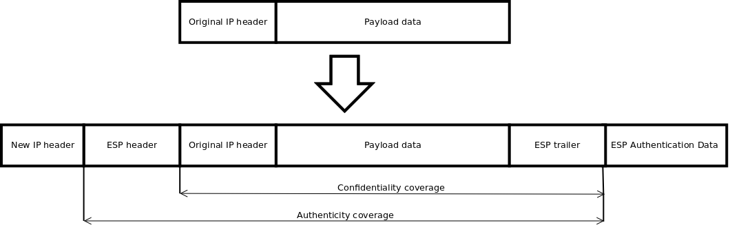
In tunnel mode original IP packet is encapsulated within a new IP packet thus securing IP payload and IP header.
RouterOS ESP supports various encryption and authentication algorithms.
- MD5
- SHA1
- SHA2 (256-bit, 512-bit)
- AES — 128-bit, 192-bit and 256-bit key AES-CBC, AES-CTR and AES-GCM algorithms;
- Blowfish — added since v4.5
- Twofish — added since v4.5
- Camellia — 128-bit, 192-bit and 256-bit key Camellia encryption algorithm added since v4.5
- DES — 56-bit DES-CBC encryption algorithm;
- 3DES — 168-bit DES encryption algorithm;
Hardware acceleration allows to do faster encryption process by using built-in encryption engine inside CPU.
* supported only 128 bit and 256 bit key sizes
** only manufactured since 2016, serial numbers that begin with number 5 and 7
*** AES-CBC and AES-CTR only encryption is accelerated, hashing done in software
**** DES is not supported, only 3DES and AES-CBC
Как настроить VPN L2TP+IpSec между MikroTik и VPS CentOS 8
Весь комплекс настройки будет разделен два два этапа:
1. Настройка VPN сервера L2TP на удаленном VPS сервере на CentOS 8
Подключение к удаленному серверу VPS будет производиться через SSH:
yum install nano mc -y
создание скрипта по установке и настройке VPN сервера L2TP+IpSec
nano vpnsetup.sh
#!/bin/sh
#
# Script for automatic setup of an IPsec VPN server on CentOS/RHEL 6, 7 and 8.
# Works on any dedicated server or virtual private server (VPS) except OpenVZ.
#
# DO NOT RUN THIS SCRIPT ON YOUR PC OR MAC!
#
# The latest version of this script is available at:
# https://github.com/hwdsl2/setup-ipsec-vpn
#
# Copyright (C) 2015-2020 Lin Song <[email protected]>
# Based on the work of Thomas Sarlandie (Copyright 2012)
#
# This work is licensed under the Creative Commons Attribution-ShareAlike 3.0
# Unported License: http://creativecommons.org/licenses/by-sa/3.0/
#
# Attribution required: please include my name in any derivative and let me
# know how you have improved it!
# =====================================================
# Define your own values for these variables
# - IPsec pre-shared key, VPN username and password
# - All values MUST be placed inside 'single quotes'
# - DO NOT use these special characters within values: \ " '
YOUR_IPSEC_PSK=''
YOUR_USERNAME=''
YOUR_PASSWORD=''
# Important notes: https://git.io/vpnnotes
# Setup VPN clients: https://git.io/vpnclients
# IKEv2 guide: https://git.io/ikev2
# =====================================================
export PATH="/usr/local/sbin:/usr/local/bin:/usr/sbin:/usr/bin:/sbin:/bin"
SYS_DT=$(date +%F-%T)
exiterr() { echo "Error: $1" >&2; exit 1; }
exiterr2() { exiterr "'yum install' failed."; }
conf_bk() { /bin/cp -f "$1" "$1.old-$SYS_DT" 2>/dev/null; }
bigecho() { echo; echo "## $1"; echo; }
check_ip() {
IP_REGEX='^(([0-9]|[1-9][0-9]|1[0-9]{2}|2[0-4][0-9]|25[0-5])\.){3}([0-9]|[1-9][0-9]|1[0-9]{2}|2[0-4][0-9]|25[0-5])$'
printf '%s' "$1" | tr -d '\n' | grep -Eq "$IP_REGEX"
}
vpnsetup() {
if ! grep -qs -e "release 6" -e "release 7" -e "release 8" /etc/redhat-release; then
echo "Error: This script only supports CentOS/RHEL 6, 7 and 8." >&2
echo "For Ubuntu/Debian, use https://git.io/vpnsetup" >&2
exit 1
fi
if [ -f /proc/user_beancounters ]; then
exiterr "OpenVZ VPS is not supported. Try OpenVPN: github.com/Nyr/openvpn-install"
fi
if [ "$(id -u)" != 0 ]; then
exiterr "Script must be run as root. Try 'sudo sh $0'"
fi
def_iface=$(route 2>/dev/null | grep -m 1 '^default' | grep -o '[^ ]*$')
[ -z "$def_iface" ] && def_iface=$(ip -4 route list 0/0 2>/dev/null | grep -m 1 -Po '(?<=dev )(\S+)')
def_state=$(cat "/sys/class/net/$def_iface/operstate" 2>/dev/null)
if [ -n "$def_state" ] && [ "$def_state" != "down" ]; then
case "$def_iface" in
wl*)
exiterr "Wireless interface '$def_iface' detected. DO NOT run this script on your PC or Mac!"
;;
esac
NET_IFACE="$def_iface"
else
eth0_state=$(cat "/sys/class/net/eth0/operstate" 2>/dev/null)
if [ -z "$eth0_state" ] || [ "$eth0_state" = "down" ]; then
exiterr "Could not detect the default network interface."
fi
NET_IFACE=eth0
fi
[ -n "$YOUR_IPSEC_PSK" ] && VPN_IPSEC_PSK="$YOUR_IPSEC_PSK"
[ -n "$YOUR_USERNAME" ] && VPN_USER="$YOUR_USERNAME"
[ -n "$YOUR_PASSWORD" ] && VPN_PASSWORD="$YOUR_PASSWORD"
if [ -z "$VPN_IPSEC_PSK" ] && [ -z "$VPN_USER" ] && [ -z "$VPN_PASSWORD" ]; then
bigecho "VPN credentials not set by user. Generating random PSK and password..."
VPN_IPSEC_PSK=$(LC_CTYPE=C tr -dc 'A-HJ-NPR-Za-km-z2-9' < /dev/urandom | head -c 20)
VPN_USER=vpnuser
VPN_PASSWORD=$(LC_CTYPE=C tr -dc 'A-HJ-NPR-Za-km-z2-9' < /dev/urandom | head -c 16)
fi
if [ -z "$VPN_IPSEC_PSK" ] || [ -z "$VPN_USER" ] || [ -z "$VPN_PASSWORD" ]; then
exiterr "All VPN credentials must be specified. Edit the script and re-enter them."
fi
if printf '%s' "$VPN_IPSEC_PSK $VPN_USER $VPN_PASSWORD" | LC_ALL=C grep -q '[^ -~]\+'; then
exiterr "VPN credentials must not contain non-ASCII characters."
fi
case "$VPN_IPSEC_PSK $VPN_USER $VPN_PASSWORD" in
*[\\\"\']*)
exiterr "VPN credentials must not contain these special characters: \\ \" '"
;;
esac
bigecho "VPN setup in progress... Please be patient."
# Create and change to working dir
mkdir -p /opt/src
cd /opt/src || exit 1
bigecho "Installing packages required for setup..."
yum -y install wget bind-utils openssl tar \
iptables iproute gawk grep sed net-tools || exiterr2
bigecho "Trying to auto discover IP of this server..."
cat <<'EOF'
In case the script hangs here for more than a few minutes,
press Ctrl-C to abort. Then edit it and manually enter IP.
EOF
# In case auto IP discovery fails, enter server's public IP here.
PUBLIC_IP=${VPN_PUBLIC_IP:-''}
[ -z "$PUBLIC_IP" ] && PUBLIC_IP=$(dig @resolver1.opendns.com -t A -4 myip.opendns.com +short)
check_ip "$PUBLIC_IP" || PUBLIC_IP=$(wget -t 3 -T 15 -qO- http://ipv4.icanhazip.com)
check_ip "$PUBLIC_IP" || exiterr "Cannot detect this server's public IP. Edit the script and manually enter it."
bigecho "Adding the EPEL repository..."
epel_url="https://dl.fedoraproject.org/pub/epel/epel-release-latest-$(rpm -E '%{rhel}').noarch.rpm"
yum -y install epel-release || yum -y install "$epel_url" || exiterr2
bigecho "Installing packages required for the VPN..."
REPO1='--enablerepo=epel'
REPO2='--enablerepo=*server-optional*'
REPO3='--enablerepo=*releases-optional*'
REPO4='--enablerepo=[Pp]ower[Tt]ools'
yum -y install nss-devel nspr-devel pkgconfig pam-devel \
libcap-ng-devel libselinux-devel curl-devel nss-tools \
flex bison gcc make ppp || exiterr2
yum "$REPO1" -y install xl2tpd || exiterr2
if grep -qs "release 6" /etc/redhat-release; then
yum -y remove libevent-devel
yum "$REPO2" "$REPO3" -y install libevent2-devel fipscheck-devel || exiterr2
elif grep -qs "release 7" /etc/redhat-release; then
yum -y install systemd-devel iptables-services || exiterr2
yum "$REPO2" "$REPO3" -y install libevent-devel fipscheck-devel || exiterr2
else
if [ -f /usr/sbin/subscription-manager ]; then
subscription-manager repos --enable "codeready-builder-for-rhel-8-*-rpms"
yum -y install systemd-devel iptables-services libevent-devel fipscheck-devel || exiterr2
else
yum "$REPO4" -y install systemd-devel iptables-services libevent-devel fipscheck-devel || exiterr2
fi
fi
bigecho "Installing Fail2Ban to protect SSH..."
yum "$REPO1" -y install fail2ban || exiterr2
bigecho "Compiling and installing Libreswan..."
SWAN_VER=3.32
swan_file="libreswan-$SWAN_VER.tar.gz"
swan_url1="https://github.com/libreswan/libreswan/archive/v$SWAN_VER.tar.gz"
swan_url2="https://download.libreswan.org/$swan_file"
if ! { wget -t 3 -T 30 -nv -O "$swan_file" "$swan_url1" || wget -t 3 -T 30 -nv -O "$swan_file" "$swan_url2"; }; then
exit 1
fi
/bin/rm -rf "/opt/src/libreswan-$SWAN_VER"
tar xzf "$swan_file" && /bin/rm -f "$swan_file"
cd "libreswan-$SWAN_VER" || exit 1
cat > Makefile.inc.local <<'EOF'
WERROR_CFLAGS = -w
USE_DNSSEC = false
USE_DH2 = true
USE_DH31 = false
USE_NSS_AVA_COPY = true
USE_NSS_IPSEC_PROFILE = false
USE_GLIBC_KERN_FLIP_HEADERS = true
EOF
if ! grep -qs IFLA_XFRM_LINK /usr/include/linux/if_link.h; then
echo "USE_XFRM_INTERFACE_IFLA_HEADER = true" >> Makefile.inc.local
fi
NPROCS=$(grep -c ^processor /proc/cpuinfo)
[ -z "$NPROCS" ] && NPROCS=1
make "-j$((NPROCS+1))" -s base && make -s install-base
cd /opt/src || exit 1
/bin/rm -rf "/opt/src/libreswan-$SWAN_VER"
if ! /usr/local/sbin/ipsec --version 2>/dev/null | grep -qF "$SWAN_VER"; then
exiterr "Libreswan $SWAN_VER failed to build."
fi
bigecho "Creating VPN configuration..."
L2TP_NET=${VPN_L2TP_NET:-'192.168.41.0/24'}
L2TP_LOCAL=${VPN_L2TP_LOCAL:-'192.168.41.1'}
L2TP_POOL=${VPN_L2TP_POOL:-'192.168.41.10-192.168.41.250'}
XAUTH_NET=${VPN_XAUTH_NET:-'192.168.43.0/24'}
XAUTH_POOL=${VPN_XAUTH_POOL:-'192.168.43.10-192.168.43.250'}
DNS_SRV1=${VPN_DNS_SRV1:-'8.8.8.8'}
DNS_SRV2=${VPN_DNS_SRV2:-'8.8.4.4'}
DNS_SRVS="\"$DNS_SRV1 $DNS_SRV2\""
[ -n "$VPN_DNS_SRV1" ] && [ -z "$VPN_DNS_SRV2" ] && DNS_SRVS="$DNS_SRV1"
# Create IPsec config
conf_bk "/etc/ipsec.conf"
cat > /etc/ipsec.conf <<EOF
version 2.0
config setup
virtual-private=%v4:10.0.0.0/8,%v4:192.168.0.0/16,%v4:172.16.0.0/12,%v4:!$L2TP_NET,%v4:!$XAUTH_NET
protostack=netkey
interfaces=%defaultroute
uniqueids=no
conn shared
left=%defaultroute
leftid=$PUBLIC_IP
right=%any
encapsulation=yes
authby=secret
pfs=no
rekey=no
keyingtries=5
dpddelay=30
dpdtimeout=120
dpdaction=clear
ikev2=never
ike=aes256-sha2,aes128-sha2,aes256-sha1,aes128-sha1,aes256-sha2;modp1024,aes128-sha1;modp1024
phase2alg=aes_gcm-null,aes128-sha1,aes256-sha1,aes256-sha2_512,aes128-sha2,aes256-sha2
sha2-truncbug=no
conn l2tp-psk
auto=add
leftprotoport=17/1701
rightprotoport=17/%any
type=transport
phase2=esp
also=shared
conn xauth-psk
auto=add
leftsubnet=0.0.0.0/0
rightaddresspool=$XAUTH_POOL
modecfgdns=$DNS_SRVS
leftxauthserver=yes
rightxauthclient=yes
leftmodecfgserver=yes
rightmodecfgclient=yes
modecfgpull=yes
xauthby=file
ike-frag=yes
cisco-unity=yes
also=shared
EOF
# Specify IPsec PSK
conf_bk "/etc/ipsec.secrets"
cat > /etc/ipsec.secrets <<EOF
%any %any : PSK "$VPN_IPSEC_PSK"
EOF
# Create xl2tpd config
conf_bk "/etc/xl2tpd/xl2tpd.conf"
cat > /etc/xl2tpd/xl2tpd.conf <<EOF
[global]
port = 1701
[lns default]
ip range = $L2TP_POOL
local ip = $L2TP_LOCAL
require chap = yes
refuse pap = yes
require authentication = yes
name = l2tpd
pppoptfile = /etc/ppp/options.xl2tpd
length bit = yes
EOF
# Set xl2tpd options
conf_bk "/etc/ppp/options.xl2tpd"
cat > /etc/ppp/options.xl2tpd <<EOF
+mschap-v2
ipcp-accept-local
ipcp-accept-remote
noccp
auth
mtu 1280
mru 1280
proxyarp
lcp-echo-failure 4
lcp-echo-interval 30
connect-delay 5000
ms-dns $DNS_SRV1
EOF
if [ -z "$VPN_DNS_SRV1" ] || [ -n "$VPN_DNS_SRV2" ]; then
cat >> /etc/ppp/options.xl2tpd <<EOF
ms-dns $DNS_SRV2
EOF
fi
# Create VPN credentials
conf_bk "/etc/ppp/chap-secrets"
cat > /etc/ppp/chap-secrets <<EOF
"$VPN_USER" l2tpd "$VPN_PASSWORD" *
EOF
conf_bk "/etc/ipsec.d/passwd"
VPN_PASSWORD_ENC=$(openssl passwd -1 "$VPN_PASSWORD")
cat > /etc/ipsec.d/passwd <<EOF
$VPN_USER:$VPN_PASSWORD_ENC:xauth-psk
EOF
bigecho "Updating sysctl settings..."
if ! grep -qs "hwdsl2 VPN script" /etc/sysctl.conf; then
conf_bk "/etc/sysctl.conf"
if [ "$(getconf LONG_BIT)" = "64" ]; then
SHM_MAX=68719476736
SHM_ALL=4294967296
else
SHM_MAX=4294967295
SHM_ALL=268435456
fi
cat >> /etc/sysctl.conf <<EOF
# Added by hwdsl2 VPN script
kernel.msgmnb = 65536
kernel.msgmax = 65536
kernel.shmmax = $SHM_MAX
kernel.shmall = $SHM_ALL
net.ipv4.ip_forward = 1
net.ipv4.conf.all.accept_source_route = 0
net.ipv4.conf.all.accept_redirects = 0
net.ipv4.conf.all.send_redirects = 0
net.ipv4.conf.all.rp_filter = 0
net.ipv4.conf.default.accept_source_route = 0
net.ipv4.conf.default.accept_redirects = 0
net.ipv4.conf.default.send_redirects = 0
net.ipv4.conf.default.rp_filter = 0
net.ipv4.conf.$NET_IFACE.send_redirects = 0
net.ipv4.conf.$NET_IFACE.rp_filter = 0
net.core.wmem_max = 12582912
net.core.rmem_max = 12582912
net.ipv4.tcp_rmem = 10240 87380 12582912
net.ipv4.tcp_wmem = 10240 87380 12582912
EOF
fi
bigecho "Updating IPTables rules..."
# Check if rules need updating
ipt_flag=0
IPT_FILE="/etc/sysconfig/iptables"
if ! grep -qs "hwdsl2 VPN script" "$IPT_FILE" \
|| ! iptables -t nat -C POSTROUTING -s "$L2TP_NET" -o "$NET_IFACE" -j MASQUERADE 2>/dev/null \
|| ! iptables -t nat -C POSTROUTING -s "$XAUTH_NET" -o "$NET_IFACE" -m policy --dir out --pol none -j MASQUERADE 2>/dev/null; then
ipt_flag=1
fi
# Add IPTables rules for VPN
if [ "$ipt_flag" = "1" ]; then
service fail2ban stop >/dev/null 2>&1
iptables-save > "$IPT_FILE.old-$SYS_DT"
iptables -I INPUT 1 -p udp --dport 1701 -m policy --dir in --pol none -j DROP
iptables -I INPUT 2 -m conntrack --ctstate INVALID -j DROP
iptables -I INPUT 3 -m conntrack --ctstate RELATED,ESTABLISHED -j ACCEPT
iptables -I INPUT 4 -p udp -m multiport --dports 500,4500 -j ACCEPT
iptables -I INPUT 5 -p udp --dport 1701 -m policy --dir in --pol ipsec -j ACCEPT
iptables -I INPUT 6 -p udp --dport 1701 -j DROP
iptables -I FORWARD 1 -m conntrack --ctstate INVALID -j DROP
iptables -I FORWARD 2 -i "$NET_IFACE" -o ppp+ -m conntrack --ctstate RELATED,ESTABLISHED -j ACCEPT
iptables -I FORWARD 3 -i ppp+ -o "$NET_IFACE" -j ACCEPT
iptables -I FORWARD 4 -i ppp+ -o ppp+ -s "$L2TP_NET" -d "$L2TP_NET" -j ACCEPT
iptables -I FORWARD 5 -i "$NET_IFACE" -d "$XAUTH_NET" -m conntrack --ctstate RELATED,ESTABLISHED -j ACCEPT
iptables -I FORWARD 6 -s "$XAUTH_NET" -o "$NET_IFACE" -j ACCEPT
# Uncomment if you wish to disallow traffic between VPN clients themselves
# iptables -I FORWARD 2 -i ppp+ -o ppp+ -s "$L2TP_NET" -d "$L2TP_NET" -j DROP
# iptables -I FORWARD 3 -s "$XAUTH_NET" -d "$XAUTH_NET" -j DROP
iptables -A FORWARD -j DROP
iptables -t nat -I POSTROUTING -s "$XAUTH_NET" -o "$NET_IFACE" -m policy --dir out --pol none -j MASQUERADE
iptables -t nat -I POSTROUTING -s "$L2TP_NET" -o "$NET_IFACE" -j MASQUERADE
echo "# Modified by hwdsl2 VPN script" > "$IPT_FILE"
iptables-save >> "$IPT_FILE"
fi
bigecho "Creating basic Fail2Ban rules..."
if [ ! -f /etc/fail2ban/jail.local ] ; then
cat > /etc/fail2ban/jail.local <<'EOF'
[ssh-iptables]
enabled = true
filter = sshd
action = iptables[name=SSH, port=ssh, protocol=tcp]
logpath = /var/log/secure
EOF
fi
bigecho "Enabling services on boot..."
if grep -qs "release 6" /etc/redhat-release; then
chkconfig iptables on
chkconfig fail2ban on
else
systemctl --now mask firewalld 2>/dev/null
systemctl enable iptables fail2ban 2>/dev/null
fi
if ! grep -qs "hwdsl2 VPN script" /etc/rc.local; then
if [ -f /etc/rc.local ]; then
conf_bk "/etc/rc.local"
else
echo '#!/bin/sh' > /etc/rc.local
fi
cat >> /etc/rc.local <<'EOF'
# Added by hwdsl2 VPN script
(sleep 15
modprobe -q pppol2tp
service ipsec restart
service xl2tpd restart
echo 1 > /proc/sys/net/ipv4/ip_forward)&
EOF
fi
bigecho "Starting services..."
# Restore SELinux contexts
restorecon /etc/ipsec.d/*db 2>/dev/null
restorecon /usr/local/sbin -Rv 2>/dev/null
restorecon /usr/local/libexec/ipsec -Rv 2>/dev/null
# Reload sysctl.conf
sysctl -e -q -p
# Update file attributes
chmod +x /etc/rc.local
chmod 600 /etc/ipsec.secrets* /etc/ppp/chap-secrets* /etc/ipsec.d/passwd*
# Apply new IPTables rules
iptables-restore < "$IPT_FILE"
# Fix xl2tpd on CentOS 7/8, if kernel module "l2tp_ppp" is unavailable
if grep -qs -e "release 7" -e "release 8" /etc/redhat-release; then
if ! modprobe -q l2tp_ppp; then
sed -i '/^ExecStartPre/s/^/#/' /usr/lib/systemd/system/xl2tpd.service
systemctl daemon-reload
fi
fi
# Restart services
mkdir -p /run/pluto
modprobe -q pppol2tp
service fail2ban restart 2>/dev/null
service ipsec restart 2>/dev/null
service xl2tpd restart 2>/dev/null
cat <<EOF
================================================
IPsec VPN server is now ready for use!
Connect to your new VPN with these details:
Server IP: $PUBLIC_IP
IPsec PSK: $VPN_IPSEC_PSK
Username: $VPN_USER
Password: $VPN_PASSWORD
Write these down. You'll need them to connect!
Important notes: https://git.io/vpnnotes
Setup VPN clients: https://git.io/vpnclients
IKEv2 guide: https://git.io/ikev2
================================================
EOF
}
## Defer setup until we have the complete script
vpnsetup "[email protected]"
exit 0
Если потребует изменить параметры сетевой адресации, нужно обратить внимание на этот раздел
L2TP_NET=${VPN_L2TP_NET:-'192.168.41.0/24'}
L2TP_LOCAL=${VPN_L2TP_LOCAL:-'192.168.41.1'}
L2TP_POOL=${VPN_L2TP_POOL:-'192.168.41.10-192.168.41.250'}
sh vpnsetup.sh
По окончанию работы скрипт выводит параметры, которые нужно использовать на MikroTik L2TP клиенте:
Server IP: 18.13.12.14
IPsec PSK: YsH8f7ke3r6i6TBB5pZu
Username: vpnuser
Password: 2FG2i3aTHm3b7soo
Для работы интернета локальной сети за MikroTik-ом, нужно поправить IPTABLES
nano /etc/sysconfig/iptables
-A POSTROUTING -s 192.168.10.0/24 -o ens3 -j MASQUERADE
-A FORWARD -s 192.168.10.0/24 -d 192.168.10.0/24 -i ppp+ -o ppp+ -j ACCEPT
systemctl restart iptables
Файл xl2tpd.conf содержит настройки VPN сервера:
nano /etc/xl2tpd/xl2tpd.conf
[global]
port = 1701
[lns default]
ip range = 192.168.41.10-192.168.41.250
local ip = 192.168.41.1
require chap = yes
refuse pap = yes
require authentication = yes
name = l2tpd
pppoptfile = /etc/ppp/options.xl2tpd
length bit = yes
добавить маршрут в сеть за MikroTik. Это правило будет отрабатывать каждый раз, когда туннель будет подниматься
nano /etc/ppp/ip-up
ip route add 192.168.10.0/24 via 192.168.41.10
192.168.10.0/24 – сеть за MikroTik
192.168.41.10 – адрес MikroTik на стороне CentOS 8.
2. Настройка L2TP клиента на MikroTik
Со стороны MikroTik нужно затронуть два раздела: PPP клиент и маршрутизацию.
Добавление L2TP клиента

/ppp profile
/interface l2tp-client
add comment=VPS-CentOS connect-to=18.13.12.14 disabled=no ipsec-secret=\
YsH8f7ke3r6i6TBB5pZu name=l2tp-out1 password=2FG2i3aTHm3b7soo profile=\
default use-ipsec=yes user=vpnuser
Успешное соединение, сопровождается статусом “R”

Добавить статический маршрут. Весь интернет трафик будет заворачиваться в VPN туннель через CentOS VPS

/ip route
add distance=1 gateway=192.168.41.1
А у прежнего интернет маршрута, необходимо понизить Distance до 2

/ip route
add distance=2 gateway=94.2.XX.YY
Таким образом весь интернет трафик будет заворачиваться на удаленный VPS, а если связь с сервером будет отсутствовать, то маршрутизация переключится на интернет провайдера.
Application Examples
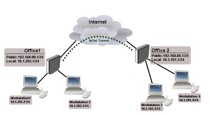
Site to Site IPsec tunnel
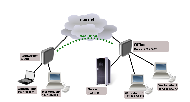
Consider setup as illustrated below. Two remote office routers are connected to internet and office workstations are behind NAT. Each office has its own local subnet, 10.1.202.0/24 for Office1 and 10.1.101.0/24 for Office2. Both remote offices needs secure tunnel to local networks behind routers.
Site 1 configuration
Start off by creating new Phase 1 profile and Phase 2 proposal entries using stronger or weaker encryption parameters that suits your needs. It is advised to create separate entries for each menu so that they are unique for each peer in case it is necessary to adjust any of the settings in the future. These parameters must match between the sites or else the connection will not establish.
/ip ipsec profile
add dh-group=modp2048 enc-algorithm=aes-128 name=ike1-site2
/ip ipsec proposal
add enc-algorithms=aes-128-cbc name=ike1-site2 pfs-group=modp2048
Continue by configuring a peer. Specify the address of the remote router. This address should be reachable through UDP/500 and UDP/4500 ports, so make sure appropriate actions are taken regarding the router’s firewall. Specify the name for this peer as well as the newly created profile.
/ip ipsec peer
add address=192.168.80.1/32 name=ike1-site2 profile=ike1-site2
/ip ipsec identity
add peer=ike1-site2 secret=thisisnotasecurepsk
![]()
Warning: If security matters, consider using IKEv2 and a different auth-method.
Lastly, create a policy which controls the networks/hosts between whom traffic should be encrypted.
/ip ipsec policy
add src-address=10.1.202.0/24 src-port=any dst-address=10.1.101.0/24 dst-port=any \
tunnel=yes action=encrypt proposal=ike1-site2 peer=ike1-site2
Site 2 configuration
Office 2 configuration is almost identical as Office 1 with proper IP address configuration. Start off by creating new Phase 1 profile and Phase 2 proposal entries.
/ip ipsec profile
add dh-group=modp2048 enc-algorithm=aes-128 name=ike1-site1
/ip ipsec proposal
add enc-algorithms=aes-128-cbc name=ike1-site1 pfs-group=modp2048
Next is the peer and identity.
/ip ipsec peer
add address=192.168.90.1/32 name=ike1-site1 profile=ike1-site1
/ip ipsec identity
add peer=ike1-site1 secret=thisisnotasecurepsk
When it is done, create a policy:
/ip ipsec policy
add src-address=10.1.101.0/24 src-port=any dst-address=10.1.202.0/24 dst-port=any \
tunnel=yes action=encrypt proposal=ike1-site1 peer=ike1-site1
At this point, the tunnel should be established and two IPsec Security Associations should be created on both routers:
/ip ipsec
active-peers print
installed-sa print
NAT and Fasttrack Bypass
To fix this we need to set up IP/Firewall/NAT bypass rule.
Office 1 router:
/ip firewall nat
add chain=srcnat action=accept place-before=0 \ src-address=10.1.202.0/24 dst-address=10.1.101.0/24
Office 2 router:
/ip firewall nat
add chain=srcnat action=accept place-before=0 \ src-address=10.1.101.0/24 dst-address=10.1.202.0/24
![]()
Note: If you previously tried to establish an IP connection before NAT bypass rule was added, you have to clear connection table from existing connection or restart both routers.
It is very important that bypass rule is placed at the top of all other NAT rules.
Another issue is if you have IP/Fasttrack enabled, packet bypasses IPsec policies. So we need to add accept rule before FastTrack.
/ip firewall filter
add chain=forward action=accept place-before=1 src-address=10.1.101.0/24 dst-address=10.1.202.0/24 connection-state=established,related
add chain=forward action=accept place-before=1 src-address=10.1.202.0/24 dst-address=10.1.101.0/24 connection-state=established,related
However, this can add significant load to router’s CPU if there is a fair amount of tunnels and significant traffic on each tunnel.
Solution is to use IP/Firewall/Raw to bypass connection tracking, that way eliminating need of filter rules listed above and reducing load on CPU by approximately 30%.
/ip firewall raw
add action=notrack chain=prerouting src-address=10.1.101.0/24 dst-address=10.1.202.0/24
add action=notrack chain=prerouting src-address=10.1.202.0/24 dst-address=10.1.101.0/24
Road Warrior setup using IKEv2 with RSA authentication
This example explains how to establish a secure IPsec connection between a device connected to the Internet (road warrior client) and a device running RouterOS acting as a server.
RouterOS server configuration
Before configuring IPsec, it is required to set up certificates. It is possible to use a separate Certificate Authority for certificate management, however in this example, self signed certificates are generated in RouterOS System/Certificates menu. Some certificate requirements should be met to connect various devices to the server:
- Common name should contain IP or DNS name of the server;
- SAN (subject alternative name) should have IP or DNS of the server;
- EKU (extended key usage) tls-server and tls-client are required.
Considering all requirements above, generate CA and server certificates:
/certificate
add common-name=ca name=ca
sign ca ca-crl-host=2.2.2.2
add common-name=2.2.2.2 subject-alt-name=IP:2.2.2.2 key-usage=tls-server name=server1
sign server1 ca=ca
Now that valid certificates are created on the router, add new Phase 1 profile and Phase 2 proposal entries with pfs-group=none.
/ip ipsec profile
add name=ike2
/ip ipsec proposal
add name=ike2 pfs-group=none
Mode config is used for address distribution from IP/Pools.
/ip pool
add name=ike2-pool ranges=192.168.77.2-192.168.77.254
/ip ipsec mode-config
add address-pool=ike2-pool address-prefix-length=32 name=ike2-conf
Since that the policy template must be adjusted to allow only specific network policies, it is advised to create a separate policy group and template.
/ip ipsec policy group
add name=ike2-policies
/ip ipsec policy
add dst-address=192.168.77.0/24 group=ike2-policies proposal=ike2 src-address=0.0.0.0/0 template=yes
Create a new IPsec peer entry which will listen to all incoming IKEv2 requests.
/ip ipsec peer
add exchange-mode=ike2 name=ike2 passive=yes profile=ike2
Identity menu allows to match specific remote peers and assign different configuration for each one of them. First, create a default identity, that will accept all peers, but will verify the peer’s identity with its certificate.
/ip ipsec identity
add auth-method=digital-signature certificate=server1 generate-policy=port-strict mode-config=ike2-conf peer=ike2 policy-template-group=ike2-policies
![]()
Note: If peer’s ID (ID_i) is not matching with the certificate it sends, the identity lookup will fail. See remote-id in identities section.
/ip ipsec mode-config
add address=192.168.66.2 address-prefix-length=32 name=usr_A split-include=192.168.55.0/24 system-dns=no
/ip ipsec identity
add auth-method=digital-signature certificate=server1 generate-policy=port-strict match-by=certificate mode-config=usr_A peer=ike2 policy-template-group=ike2-policies remote-certificate=rw-client1
Split tunnel configuration
Split tunneling is a method which allows road warrior clients to only access a specific secured network and at the same time send the rest of the traffic based on their internal routing table (as opposed to sending all traffic over the tunnel). To configure split tunneling, changes to mode config parameters are needed.
For example we will allow our road warrior clients to only access 10.5.8.0/24 network.
/ip ipsec mode-conf
set [find name="rw-conf"] split-include=10.5.8.0/24
It is also possible to send specific DNS server for the client to use. By default system-dns=yes is used, which sends DNS servers that are configured on the router itself in IP/DNS. We can force the client to use different DNS server by using the static-dns parameter.
/ip ipsec mode-conf
set [find name="rw-conf"] system-dns=no static-dns=10.5.8.1
While it is possible to adjust IPsec policy template to only allow road warrior clients to generate policies to network configured by split-include parameter, this can cause compatibility issues with different vendor implementations (see known limitations). Instead of adjusting the policy template, allow access to secured network in IP/Firewall/Filter and drop everything else.
/ip firewall filter
add action=drop chain=forward src-address=192.168.77.0/24 dst-address=!10.5.8.0/24
![]()
Warning: Split networking is not a security measure. The client (initiator) can still request a different Phase 2 traffic selector.
Generating client certificates
To generate a new certificate for the client and sign it with previously created CA.
/certificate
add common-name=rw-client1 name=rw-client1 key-usage=tls-client
sign rw-client1 ca=ca
PKCS12 format is accepted by most of client implementations, so when exporting the certificate, make sure PKCS12 is specified.
/certificate
export-certificate rw-client1 export-passphrase=1234567890 type=pkcs12
A file named cert_export_rw-client1.p12 is now located in the routers System/File section. This file should be securely transported to the client device.
Typically PKCS12 bundle contains also CA certificate, but some vendors may not install this CA, so self-signed CA certificate must be exported separately using PEM format.
/certificate
export-certificate ca type=pem
A file named cert_export_ca.crt is now located in the routers System/File section. This file should also be securely transported to the client device.
PEM is another certificate format for use in client software that do not support PKCS12. Principle is pretty much the same.
/certificate
export-certificate ca
export-certificate rw-client1 export-passphrase=1234567890
Three files are now located in the routers Files section: cert_export_ca.crt, cert_export_rw-client1.crt and cert_export_rw-client1.key which should be securely transported to the client device.
Here is a list of known limitations by popular client software IKEv2 implementations.
- Windows will always ignore networks received by split-include and request policy with destination 0.0.0.0/0 (TSr). When IPsec-SA is generated, Windows requests DHCP option 249 to which RouterOS will respond with configured split-include networks automatically.
- Both Apple macOS and iOS will only accept the first split-include network.
- Both Apple macOS and iOS will use the DNS servers from system-dns and static-dns parameters only when 0.0.0.0/0 split-include is used.
- While some implementations can make use of different PFS group for phase 2, it is advised to use pfs-group=none under proposals to avoid any compatibility issues.
RouterOS client configuration
Import a PKCS12 format certificate in RouterOS.
/certificate import file-name=cert_export_RouterOS_client.p12 passphrase=1234567890
There should now be the self-signed CA certificate and the client certificate in Certificate menu. Find out the name of the client certificate.
/certificate print
cert_export_RouterOS_client.p12_0 is the client certificate.
It is advised to create a separate Phase 1 profile and Phase 2 proposal configurations to not interfere with any existing IPsec configuration.
/ip ipsec profile
add name=ike2-rw
/ip ipsec proposal
add name=ike2-rw pfs-group=none
While it is possible to use the default policy template for policy generation, it is better to create a new policy group and template to separate this configuration from any other IPsec configuration.
/ip ipsec policy group
add name=ike2-rw
/ip ipsec policy
add group=ike2-rw proposal=ike2-rw template=yes
Create a new mode config entry with responder=no that will request configuration parameters from the server.
/ip ipsec mode-config
add name=ike2-rw responder=no
Lastly, create peer and identity configurations.
/ip ipsec peer
add address=2.2.2.2/32 exchange-mode=ike2 name=ike2-rw-client
/ip ipsec identity
add auth-method=digital-signature certificate=cert_export_RouterOS_client.p12_0 generate-policy=port-strict mode-config=ike2-rw peer=ike2-rw-client policy-template-group=ike2-rw
Verify that the connection is successfully established.
/ip ipsec
active-peers print
installed-sa print
Enabling dynamic source NAT rule generation
If we look at the generated dynamic policies, we see that only traffic with a specific (received by mode config) source address will be sent through the tunnel. But a router in most cases will need to route a specific device or network through the tunnel. In such case we can use source NAT to change the source address of packets to match the mode config address. Since the mode config address is dynamic, it is impossible to create static source NAT rule. In RouterOS it is possible to generate dynamic source NAT rules for mode config clients.
For example, we have a local network 192.168.88.0/24 behind the router and we want all traffic from this network to be sent over the tunnel. First of all, we have to make a new IP/Firewall/Address list which consists of our local network.
/ip firewall address-list
add address=192.168.88.0/24 list=local
When it is done, we can assign newly created IP/Firewall/Address list to mode config configuration.
/ip ipsec mode-config
set [ find name=ike2-rw ] src-address-list=local
Verify correct source NAT rule is dynamically generated when the tunnel is established.
[admin@MikroTik] > /ip firewall nat print
Flags: X - disabled, I - invalid, D - dynamic 0 D ;;; ipsec mode-config chain=srcnat action=src-nat to-addresses=192.168.77.254 src-address-list=local dst-address-list=!local
![]()
Warning: Make sure dynamic mode config address is not a part of local network.
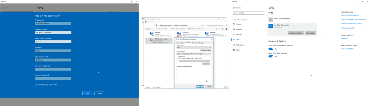
Windows client configuration

You can now proceed to Network and Internet settings -> VPN and add a new configuration. Fill in the Connection name, Server name or address parameters. Select IKEv2 under VPN type. When it is done, it is necessary to select «Use machine certificates». This can be done in Network and Sharing Center by clicking the Properties menu for the VPN connection. The setting is located under Security tab.
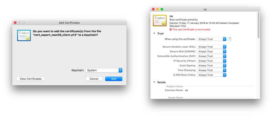
macOS client configuration
Open PKCS12 format certificate file on the macOS computer and install the certificate in «System» keychain. It is necessary to mark the CA certificate as trusted manually since it is self-signed. Locate the certificate macOS Keychain Access app under System tab and mark it as Always Trust.
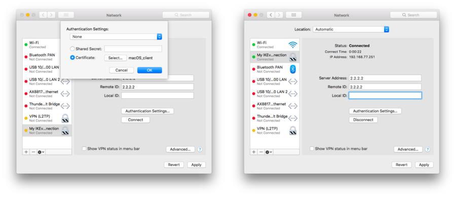
You can now proceed to System Preferences -> Network and add a new configuration by clicking the + button. Select Interface: VPN, VPN Type: IKEv2 and name your connection. Remote ID must be set equal to common-name or subjAltName of server’s certificate. Local ID can be left blank. Under Authentication Settings select None and choose the client certificate. You can now test the connectivity.
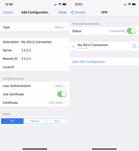
iOS client configuration
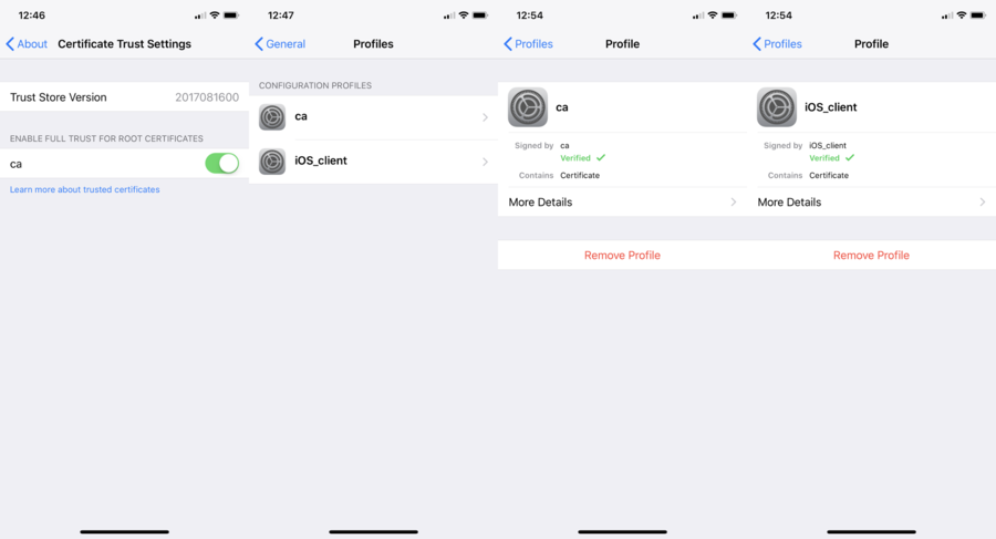
You can now proceed to Settings -> General -> VPN menu and add a new configuration. Remote ID must be set equal to common-name or subjAltName of server’s certificate. Local ID can be left blank.
![]()
Note: If you are connected to the VPN over WiFi, the iOS device can go into sleep mode and disconnect from the network.
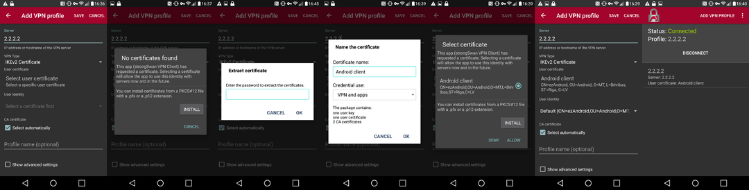
Android (strongSwan) client configuration
Linux (strongSwan) client configuration
Download the PKCS12 certificate bundle and move it to /etc/ipsec.d/private directory.
Add exported passphrase for the private key to /etc/ipsec.secrets file where «strongSwan_client.p12» is the file name and «1234567890» is the passphrase.
: P12 strongSwan_client.p12 "1234567890"
Add a new connection to /etc/ipsec.conf file
conn "ikev2" keyexchange=ikev2 ike=aes128-sha1-modp2048 esp=aes128-sha1 leftsourceip=%modeconfig leftcert=strongSwan_client.p12 leftfirewall=yes right=2.2.2.2 rightid="CN=2.2.2.2" rightsubnet=0.0.0.0/0 auto=add
You can now restart (or start) the ipsec daemon and initialize the connection
$ ipsec restart
$ ipsec up ikev2
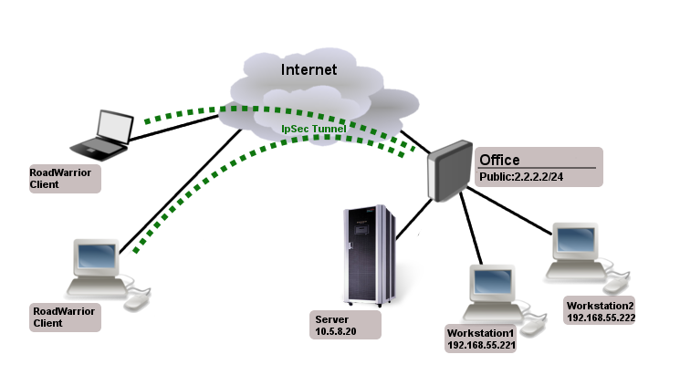
Road Warrior setup with Mode Conf
Consider setup where worker need to access other co-workers (workstations) and local office server remotely.
Office has two subnets:
- 192.168.55.0/24 for workstations
- 192.168.66.0/24 network that must not be reachable by RoadWarrior clients
- 10.5.8.0/24 for servers
And access to those networks should be secure.
Mode Conf, policy group and policy templates will allow us to overcome these problems.
IPsec Server Config
At first we need a pool from which RoadWarrior will will get an address. Typically in office you set up DHCP server for local workstations, the same DHCP pool can be used.
/ip pool
add name=ipsec-RW ranges=192.168.77.2-192.168.77.254
Next we need to set up what settings to send to the client using Mode Conf.
/ip ipsec mode-config
add address-pool=ipsec-RW name=RW-cfg split-include=\ 10.5.8.0/24,192.168.55.0/24
As you can see we specified from which pool to give out address and two allowed subnets.
Now to allow only specific source/destination address in generated policies we will use policy group and create policy templates:
/ip ipsec policy group
add name=RoadWarrior
/ip ipsec policy
add dst-address=192.168.77.0/24 group=RoadWarrior src-address=10.5.8.0/24 \ template=yes
add dst-address=192.168.77.0/24 group=RoadWarrior src-address=192.168.55.0/24 \ template=yes
/ip ipsec user
add name=user1 password=123
add name=user2 password=234
/ip ipsec peer
add auth-method=pre-shared-key-xauth generate-policy=port-strict mode-config=RW-cfg \ policy-template-group=RoadWarrior secret=123 passive=yes
Apple iOS (iPhone/iPad) Client
For iOS devices to be able to connect, proposal changes are needed:
- does not work with 3des encryption algorithm, aes-128/256 works
- auth algorithm must be sha1
- PFS group must be none
- lifetime must be 8 hours
Example of valid proposal configuration for iOS devices:
/ip ipsec proposal
set default enc-algorithms=aes-128-cbc,aes-256-cbc lifetime=8h \ pfs-group=none
![]()
Note: Iphone does not work with split-include 0.0.0.0/0. If you set 0.0.0.0/0 for older clients traffic will not be sent over the tunnel, for newer ios clients tunnel will not be established.
Android Client Notes
Android devices are trying to add policy with destination 0.0.0.0/0, so you have to make sure that correct policy template is added.
In our case we need to add:
/ip ipsec policy
add group=RoadWarrior dst-address=192.168.77.0/24 src-address=0.0.0.0/0 template=yes
RouterOS Client Config
/ip ipsec peer
add address=2.2.2.2 auth-method=pre-shared-key-xauth generate-policy=port-strict secret=123 \ xauth-login=user1 xauth-password=123 mode-config=request-only
Shrew Client Config
n:version:2
n:network-ike-port:500
n:network-mtu-size:1380
n:network-natt-port:4500
n:network-natt-rate:15
n:network-frag-size:540
n:network-dpd-enable:0
n:client-banner-enable:0
n:network-notify-enable:0
n:client-wins-used:0
n:client-wins-auto:1
n:client-dns-used:1
n:client-dns-auto:0
n:client-splitdns-used:1
n:client-splitdns-auto:0
n:phase1-dhgroup:2
n:phase1-life-secs:86400
n:phase1-life-kbytes:0
n:vendor-chkpt-enable:0
n:phase2-life-secs:300
n:phase2-life-kbytes:0
n:policy-nailed:1
n:policy-list-auto:1
n:client-addr-auto:1
s:network-host:2.2.2.2
s:client-auto-mode:pull
s:client-iface:virtual
s:network-natt-mode:disable
s:network-frag-mode:disable
s:auth-method:mutual-psk-xauth
s:ident-client-type:address
s:ident-server-type:address
b:auth-mutual-psk:MTIz
s:phase1-exchange:main
s:phase1-cipher:3des
s:phase1-hash:md5
s:phase2-transform:esp-3des
s:phase2-hmac:sha1
s:ipcomp-transform:disabled
n:phase2-pfsgroup:2
s:policy-level:require
Basic L2TP/IPsec setup
This example demonstrates how to easily setup L2TP/IPsec server on RouterOS for road warrior connections (works with Windows, Android, iOS, macOS and other vendor L2TP/IPsec implementations).
RouterOS server configuration
First step is to enable L2TP server:
/interface l2tp-server server
set enabled=yes use-ipsec=required ipsec-secret=mySecret default-profile=default
use-ipsec is set to required to make sure that only IPsec encapsulated L2TP connections are accepted.
Now what it does is enables L2TP server and creates dynamic IPsec peer with specified secret.
[admin@MikroTik] /ip ipsec peer> print 0 D address=0.0.0.0/0 local-address=0.0.0.0 passive=yes port=500 auth-method=pre-shared-key secret="123" generate-policy=port-strict exchange-mode=main-l2tp send-initial-contact=yes nat-traversal=yes hash-algorithm=sha1 enc-algorithm=3des,aes-128,aes-192,aes-256 dh-group=modp1024 lifetime=1d dpd-interval=2m dpd-maximum-failures=5
![]()
Note: Care must be taken if static IPsec peer configuration exists.
/ip pool add name=vpn-pool range=192.168.99.2-192.168.99.100
/ppp profile
set default local-address=192.168.99.1 remote-address=vpn-pool
/ppp secret
add name=user1 password=123
add name=user2 password=234
Now router is ready to accept L2TP/IPsec client connections.
RouterOS client configuration
For RouterOS to work as L2TP/IPsec client, it is as simple as adding a new L2TP client.
/interface l2tp-client
add connect-to=1.1.1.1 disabled=no ipsec-secret=mySecret name=l2tp-out1 \ password=123 use-ipsec=yes user=user1
It will automatically create dynamic IPsec peer and policy configuration.
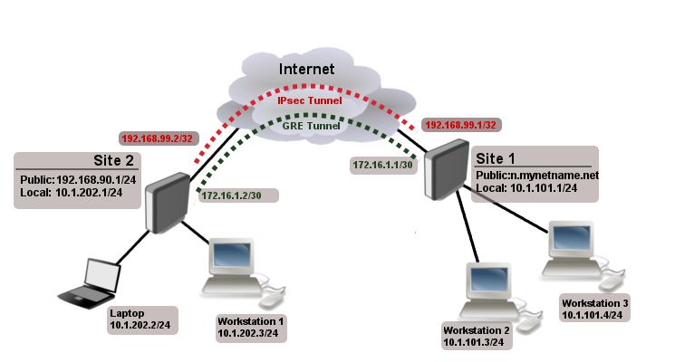
Site to Site GRE tunnel over IPsec (IKEv2) using DNS
This example explains how it is possible to establish a secure and encrypted GRE tunnel between two RouterOS devices when one or both sites do not have a static IP address. Before making this configuration possible, it is necessary to have a DNS name assigned to one of the devices which will act as a responder (server). For simplicity, we will use RouterOS built in DDNS service IP/Cloud.
Site 1 (server) configuration
This is the side that will listen to incoming connections and act as a responder. We will use mode config to provide an IP address for the second site, but first create a loopback (blank) bridge and assign an IP address to it that will be used later for GRE tunnel establishment.
/interface bridge
add name=loopback
/ip address
add address=192.168.99.1 interface=loopback
/ip ipsec profile
add dh-group=ecp256,modp2048,modp1024 enc-algorithm=aes-256,aes-192,aes-128 name=ike2
/ip ipsec proposal
add auth-algorithms=null enc-algorithms=aes-128-gcm name=ike2-gre pfs-group=none
Next, create new mode config entry with responder=yes. This will provide an IP configuration for the other site as well as the host (loopback address) for policy generation.
/ip ipsec mode-config
add address=192.168.99.2 address-prefix-length=32 name=ike2-gre split-include=192.168.99.1/32 system-dns=no
It is advised to create a new policy group to separate this configuration from any existing or future IPsec configuration.
/ip ipsec policy group
add name=ike2-gre
Now it is time to set up a new policy template that will match the remote peers new dynamic address and the loopback address.
/ip ipsec policy
add dst-address=192.168.99.2/32 group=ike2-gre proposal=ike2-gre src-address=192.168.99.1/32 template=yes
The next step is to create peer configuration that will listen for all IKEv2 requests. If you already have such entry, you can skip this step.
/ip ipsec peer
add exchange-mode=ike2 name=ike2 passive=yes profile=ike2
/ip ipsec identity
add generate-policy=port-strict mode-config=ike2-gre peer=ike2 policy-template-group=ike2-gre secret=test
The last step is to create the GRE interface itself. This can also be done later when IPsec connection is established from the client side.
/interface gre
add local-address=192.168.99.1 name=gre-tunnel1 remote-address=192.168.99.2
Site 2 (client) configuration
Similarly to server configuration, start off by creating new Phase 1 profile and Phase 2 proposal configurations. Since this side will be the initiator, we can use more specific profile configuration to control which exact encryption parameters are used, just make sure they overlap with what is configured on the server side.
/ip ipsec profile
add dh-group=ecp256 enc-algorithm=aes-256 name=ike2-gre
/ip ipsec proposal
add auth-algorithms=null enc-algorithms=aes-128-gcm name=ike2-gre pfs-group=none
Next, create new mode config entry with responder=no. This will make sure the peer requests IP and split-network configuration from the server.
/ip ipsec mode-config
add name=ike2-gre responder=no
It is also advised to create a new policy group to separate this configuration from any existing or future IPsec configuration.
/ip ipsec policy group
add name=ike2-gre
Create a new policy template on the client side as well.
/ip ipsec policy
add dst-address=192.168.99.1/32 group=ike2-gre proposal=ike2-gre src-address=192.168.99.2/32 template=yes
Move on to peer configuration. Now we can specify the DNS name for the server under address parameter. Obviously, you can use an IP address as well.
/ip ipsec peer
add address=n.mynetname.net exchange-mode=ike2 name=p1.ez profile=ike2-gre
Lastly, create an identity for our newly created peer.
/ip ipsec identity
add generate-policy=port-strict mode-config=ike2-gre peer=p1.ez policy-template-group=ike2-gre secret=test
If everything was done properly, there should be a new dynamic policy present.
/ip ipsec policy print
Flags: T - template, X - disabled, D - dynamic, I - invalid, A - active, * - default 0 T * group=default src-address=::/0 dst-address=::/0 protocol=all proposal=default template=yes 1 T group=ike2-gre src-address=192.168.99.2/32 dst-address=192.168.99.1/32 protocol=all proposal=ike2-gre template=yes 2 DA src-address=192.168.99.2/32 src-port=any dst-address=192.168.99.1/32 dst-port=any protocol=all action=encrypt level=unique ipsec-protocols=esp tunnel=yes sa-src-address=172.17.2.1 sa-dst-address=172.17.2.2 proposal=ike2-gre ph2-count=1
A secure tunnel is now established between both sites which will encrypt all traffic between 192.168.99.2 <=> 192.168.99.1 addresses. We can use these addresses to create a GRE tunnel.
/interface gre
add local-address=192.168.99.2 name=gre-tunnel1 remote-address=192.168.99.1
IKEv2 EAP between NordVPN and RouterOS
Example available here
Дополнительные опции L2TP-клиента
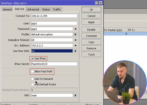
В настройках L2TP-клиента можно указать «Src. Address» на вкладке «Dial Out»:
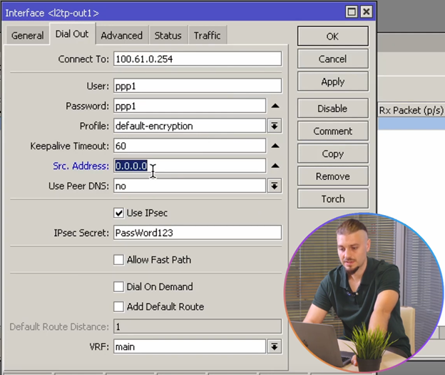
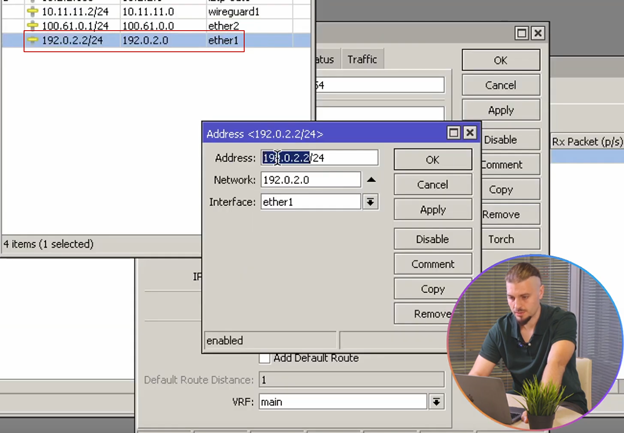
С какого адреса подключаться нашему клиенту, например, mikrotik имеет несколько внешних адресов:
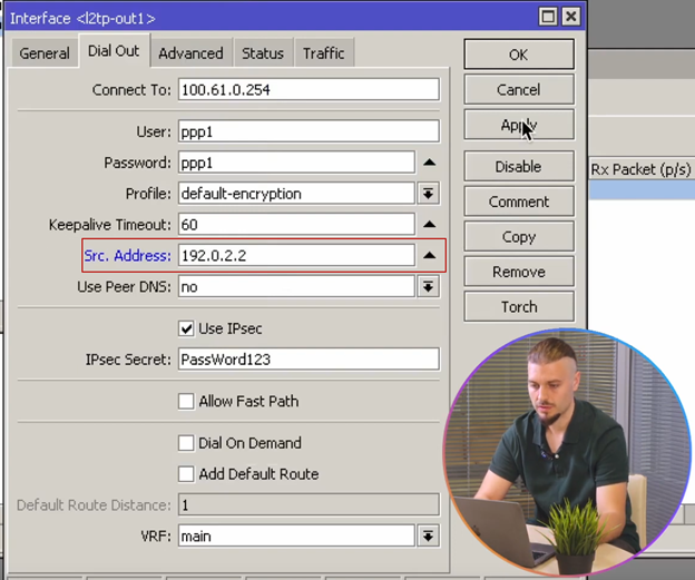
Можем настроить, чтобы наш клиент подключался только с конкретного адреса, например, 192.0.2.2:
Следующая опция использовать одноранговый DNS (Use peer DNS), т.е. DNS, получаемый от сервера L2TP, опция имеет три варианта:
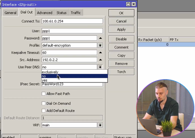
«exclusively» — исключительно, т. е. вне зависимости от системных настроек, будет использован DNS-сервер, полученный от L2TP-сервера, «no» — нет, «yes» — да. Опции «Use IPsec» и «Allow Fast Path» подробно рассмотрены в ролике про L2TP-сервер «ССЫЛКА на инструкцию»
«Dial On Demand» — подключаться при использовании.
«Add Default Route» — добавлять, как маршрут по умолчанию.
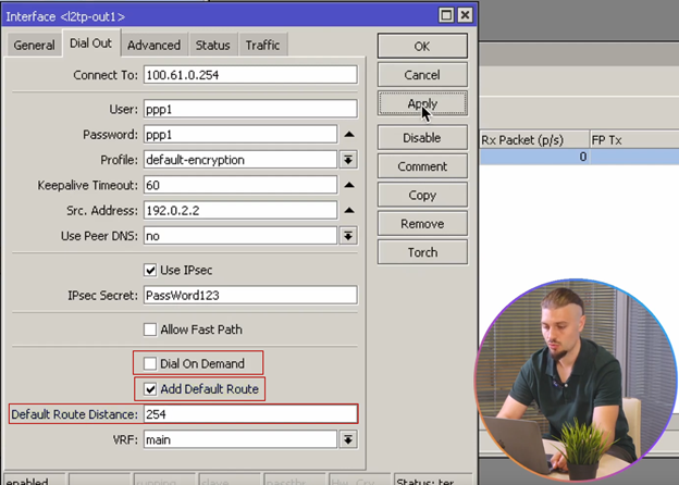
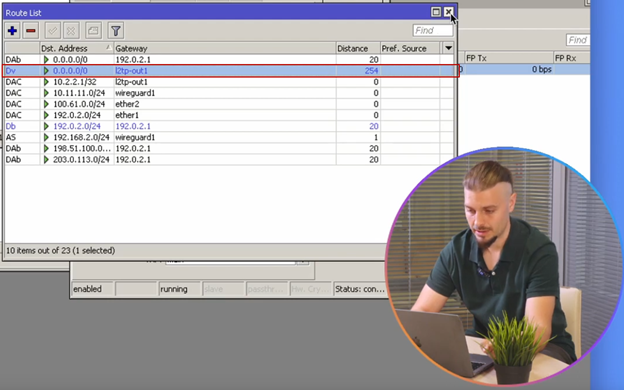
При включении опции, добавляется ещё один маршрут в таблицу маршрутизации со статусом «Dv» (dynamic vpn), чтобы он не помешал существующим подключениям. Укажем «Default Route Distance» равной 254, её действие аналогично метрике в таблице маршрутизации Windows. Чем больше значение, тем ниже приоритет у маршрута:
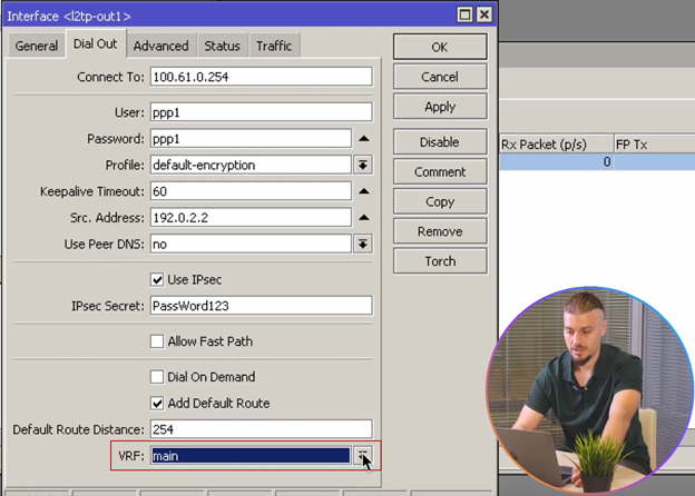
В RouterOS 7 появилась возможность выбора таблицы маршрутизации:
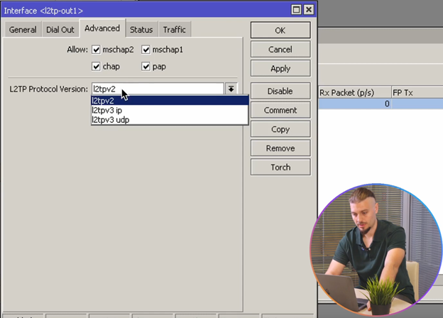
В разделе «Advanced» в RouterOS 7 появились опции, связанные с аутентификацией и версий L2TP протокола, который позволяет версии «l2tpv3» работать на уровне L2:
На этом, настройка L2tp Client закончена.
